Remote Auto
Tuner Command for IC7700 and IC7800
Jeff VE1ZAC
Nov 2012
The
IC7700 and other Icom transceivers have no built in remote tuner call command
to use with antennas that have a remote tuner at their base, such as an MFJ 998RT
or other device. This is a decided nuisance as each time you want the remote
tuner to adjust itself you have to go through a laborious series of steps to
initiate a low power transmit signal, let the remote autotuner do its thing,
and then revert back to whatever the rig was doing beforehand. Many
transceivers have this built into a routine in the transceivers command set,
but not Icom, for some reason. This makes it a pain to utilize these new auto
tuners as remote antenna feed point matchers.
Lately,
I have converted my low band transmit antenna to a 55 foot vertical with a short wire coming off
the top in ‘L’ configuration, working against a hodge podge of radials spread
around the base and my yard. I wanted to use this antenna with a solid state amp
for 800 watts, and from 160M to 40M. There is a switchable 18 UH loading coil
available at the base for 160M use. Recently, I purchased a shiny new MFJ 998RT
from DX Engineering to sit at the base of this antenna. I also have a regular
MFJ 998 sitting in the shack for use with a beam and other antennas. I decided
to leave the 998 in place with my ALS 1300 amp for the other antennas for amp
protection. The amp output is switched from the 998 to the 998RT for low band
transmit use.
Previously,
I had used an Arduino to make an interface for the 998 and my IC7700 to emulate
the missing AH3 tuner interface. I decided to convert this device to provide
the missing tuner call command which would allow it to cause any autotuner
employed to initiate the needed self-matching function. In my case, both auto
tuners needed a 15 watt signal to do this. I also mounted my device to the
convenient rack mounting bracket on the left of the transceiver to make this
tuner command button easily accessible. The rigs SWR meter is used to check the
remote tuner function.
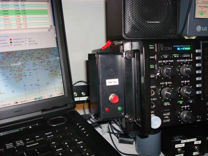
Figure
1: New remote
tuner call button on side of IC7700
Previously,
I had established communication with the Icom CI-V line and the Arduino and
found no need to re visit this function. I did have to re work receiving data
from IC7700 and found some excellent code written by Jean-Jacques ON7EQ which
worked better than mine. I helped myself to his Arduino code with some modifications. Thanks Jean-Jacques
!
The
steps needed for this new routine:
1) Wait
for a push button event
2) Read
the existing mode and power of the transceiver, and store these
3) Turn
off internal auto tuner function
4) Activate
control relay to interrupt amp control line
5) Turn on
a red LED on box
6) Switch
to RTTY and low power( 15 watts for MFJ 998 and 998RT)
7) Turn
transmit on, and wait for second push button event. (You control time this is
on by watching the rig SWR meter.. when SWR is low, push button again) In any
caser, there is a built in limit of time on of 4 seconds.
8) Turn
Red led off, and turn green led on
9) Turn
auto tuner functions back on, and initiate a 2 second RTTY transmission to
allow rig internal auto tuner to adjust. (This is done by rig)
10) Turn
Green led off
11) Put
original mode and power back in place and wait for push button call again.
I
decided to make the remote tune time manual because the tuner takes some time
to adjust when first setup. I think eventually, once you have done tunes on a
bunch of bands, you could fix this to a 2 second transmit time and make it
happen by Arduino control 100% but for now I am doing it this way to see how
the remote tuner function works. It also means you have to pay a little
attention to what is going on, which isn’t a bad thing.
I
have found this routine to work quite well with the com speed set to 9600 baud.
The built in delays in my code are quite critical. I would leave them in unless
you find some other scheme to work. Your rig needs to have “Transceive” shut
off in the CI-V control menu settings, and 9600 baud set for baudrate. With no
computer rig control running, the tune call works perfectly. However, if you
have rig control software running, you have to be careful as there will be
collisions and conflicts with the rig control software.
I
have tested my device as follows:
DXLab
suite.. set interrogate time to > 500 mS, and VFO repeat rate to slow. Do
not verify command sequences.
N1MM..
works on default settings.
N3FJP contest software.. works well with
interrogate time set to 2 seconds.
The circuit:
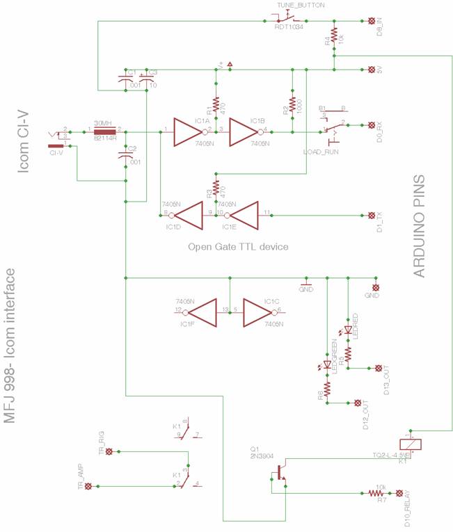
Figure 2: Arduino Icom tune control
(**error..D10_relay should be D11_relay)
I
added a small Panasonic form 2 sized 4.5 volt relay for the amp control line
interrupter. This relay comes with a built in anti free wheel diode. If your
relay does not have one, remember to add one in parallel with the relay coil to
snub the reverse switching spike. Any NPN switching transistor can be used to
control the relay.
My
circuit is built on an experimenter shield which plugs on top of the Arduino.
There
are some notes in my previous article about interfacing to the CI-V line for
serial communications so I won’t repeat them here. The switch marked ‘Load_Run’
is used only when loading software to the Arduino. Normally it is left in the
‘Run’ position.
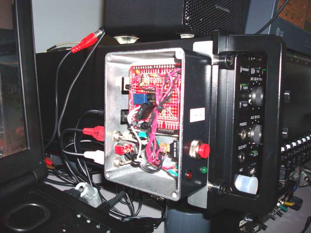
Figure
3: Inside the control
box. The Arduino is under the red experimenter shield
Naturally,
the Arduino code can be changed anytime by plugging in a USB cable to your
computer. I power my tuner call setup
from the auxiliary power output on the IC7700.
Here is the code: (note, if you would like me to send
you the code file, send a request to jeffh dot smith at gmail dot com)
// An Arduino based command sequencer for IC7700 and 7800 ( and others)
//Allows use of remote tuner like MFK927 or MFJ 998 or 998RT
//Set the low power level to suit your tuner
// VE1ZAC Jeff Smith Nov 23,2012
// If you would like code file, send request to
//jeffh dot smith at gmail dot com
//
//
// Nov 13, 2012, re wrote with working mode and power routines from
ON7EQ
//Thanks to Jean-Jacques for better ICOM interrogation than mine !
//This one stores power and mode and returns rig to the stored values
when done
// Routine stores power and mode, switches to RTTY and low power,
//sends low power out while remote tuner is adjusting, manually stopped
//and then rig resets tuner functions and does an autot tune, then
resets mode a
// NOTE.. DXLab, N1MM and N3FLP contest software all work at 9600 baud
and min o
//500 mSec interrogation time. 1 second is even better
//This is the E1 control version
// Works OK with Commander , and 500 ms
//command interval, continuous interrogate on
// *** Note, this is for IC7700 , IC7800 but should work with any
//Icom that does not have AH3-4 remote tuner connection.
//all built in delays are important, may not run right if any are
changed.
// this one for NC tune push button
// Includes control of a relay to open the transmit line controlling
amplifier
//Involves 1st PB push starting cycle and sending out low power
//When SWR reaches low level, push button again to stop
//Auto tuner startup will be automatic for rig tuner
//You can skip the rig auto tuner by inserting a goto skiptune where
needed
//at end of mode and power replacement
#define TuneRequestPin 8/ / t h e P B o n u n i t to start process
#define GREEN 12/ / L E D p i n ,
#define RED 13/ / L E D p i n ,
#define RELAY 11/ / T r a n s m i t c o n t r ol line relay, disable amp
;
// These are all the command arrays needed
//array elements are DEC versions of HEX command
// add more as needed and transmit in array loop
int i;
int incoming;
int buffget[10];
int ActMode =0;
int ActPwr_msb=0;
int ActPwr_lsb=0;
long TuneRequestPinbuttonTime = 0;
long lastCAT = 0;
int TxAddress=110;
int LowPowerSet = 40;/ / set tune power here Currently 15 watts for MFJ 998 s
int read_trx_id[6] = {254,254,TxAddress,225,25,253};
int mode_read[6] = {254,254,TxAddress,225,04,253};
int rf_power_read[7] = {254,254,TxAddress,225,20,10,253};
int low_power[9] ={254,254,TxAddress,225,20,10,00,LowPowerSet,253};
int tx[8] ={254,254,TxAddress,225,28,00,01,253};
int rx[8] ={254,254,TxAddress,225,28,00,00,253};
int mode_fm[7] ={254,254,TxAddress,225,6,5,253};
int mode_rtty[7] ={254,254,TxAddress,225,6,4,253};
int mode_return[5] ={254,254,TxAddress,225,6};
int rf_power_set[6] = {254,254,TxAddress,225,20,10};
int autooff[10] = {254,254,TxAddress,225,26,5,0,113,0,253};
int tuneon[8] = {254,254,TxAddress,225,28,1,1,253};
int tuneoff[8] = {254,254,TxAddress,225,28,01,00,253};
int autoon[10]={254,254,TxAddress,225,26,5,0,113,1,253};
int TuneRequestPin_status = LOW; // Low level is idle
int ActFilter = 0;
// This loop run once on start up to set up things
void setup() {
pinMode (TuneRequestPin, INPUT);
pinMode (GREEN, OUTPUT);
pinMode (RED, OUTPUT);
pinMode (RELAY, OUTPUT);
digitalWrite(RELAY, LOW);
digitalWrite(GREEN, LOW); //turn green
led off
digitalWrite(RED, LOW); // turn red
led off
Serial.begin(9600);
}
// MAIN LOOP
void loop() {
// Wait for push button
waitbutton:
TuneRequestPin_status = digitalRead(TuneRequestPin);
if (TuneRequestPin_status
== LOW) {
TuneRequestPinbuttonTime = millis(); // reset timer
goto waitbutton;
}
if ((millis() -
TuneRequestPinbuttonTime) > 50) goto waitbutton;
// we have a button event !
digitalWrite (RED, HIGH); //
turn on red led
delay(50);
// get the mode and store it
mode_request:
while(Serial.available() > 0)S e rial.read(); //clear
buffer
delay(20);
for (i=0;i<6;i++){
Serial.write(mode_read[i]
); }
delay(1);
m_next:
if(Serial.available() >0) {
incoming = Serial.read(); //1st
if (incoming
==254) goto m_start;
goto m_next; }
m_start:
Serial.println("254");
buffget[0] = 0;
for(i=0;
i<7; i++) {/ / g et next 7
if(Serial.available() >0) {
buffget[i] = Serial.read();
delay(2);
}
}
delay(20); // ** important delay to allow buffer to fill
if((buffget[0]
== 254) and (buffget[3] == 4) and (buffget[6] == 253)) goto mode;
goto mode_request;
mode:
delay(5); // ** don't change this delay
ActMode = buffget[4];
ActFilter= buffget[5];
Serial.println(ActMode);
Serial.print("
");
Serial.println(ActFilter);
// get rf power level
pwr_request:
while(Serial.available() > 0)S e rial.read(); //clear
buffer
delay(20);
for(i=0;
i<7; i++) {
Serial.write(rf_power_read[i]);
} //
send pwr request
delay(1);
// get power reply
pwr_next:
if(Serial.available() >0) {
incoming = Serial.read();
if(incoming
== 254) goto pwr_start;
goto pwr_next; }
pwr_start:
Serial.println("p254");
buffget[0] =0;
for (i=0; i<8;i++) {
if(Serial.available() >0) {
buffget[i] = Serial.read();
delay(2);
}
}
delay(20); // *** important buff process delay
if((buffget[0]
== 254) and (buffget[3] ==20) and (buffget[4] ==10) and (buffget[
goto pwr_request;
read_power:
ActPwr_msb = buffget[5];
ActPwr_lsb = buffget[6];
Serial.println("
power");
digitalWrite (RELAY, HIGH);
// now do tune procedure
//Turn off tuner
delay(5);
for (i=0; i<8; i++) {/ / d i sable autotuner
Serial.write(tuneoff[i]);
}
delay(50);
for (i=0; i<10; i++) {/ / d i sable auto
Serial.write (autooff[i]);
}
delay(50);
for(i=0;i<7;i++)
{
Serial.write(mode_rtty[i]
); } //
goto rtty mode
delay(50);
for(i=0;i<9;i++){
Serial.write(low_power[i]
); } //
goto low power
delay(50);
for(i=0;i<8;i++)
{
Serial.write(tx[i]); } // tx on
delay(50);
Serial.println("wait
2nd button");
TuneRequestPin_status = LOW;
delay(2);
//2nd push button wait routine
waitbutton2:
TuneRequestPin_status = digitalRead(TuneRequestPin);
if (TuneRequestPin_status
== LOW) {
TuneRequestPinbuttonTime = millis(); // reset timer
goto waitbutton2;
}
if ((millis() - TuneRequestPinbuttonTime)
> 50) goto waitbutton2;
delay(20);
Serial.println(" Stop
tune");
delay(20);
// we have a button event !
while(Serial.available() > 0)S e rial.read(); //clear
buffer
delay(20);
for(i=0;i<8;i++)
{
Serial.write(rx[i]); } // turn off
Transmit
delay(50);
digitalWrite (RED, LOW); // turn off
red led
delay(20);
for (i=0; i<8; i++) {/ / e n able autotuner
Serial.write (tuneon[i]); }
delay(50);
for (i=0; i<10; i++) {/ / e n able auto
Serial.write (autoon[i]); }
delay(500);
// Put tuner in gear and give it a blast
// Green LED on
digitalWrite (GREEN, HIGH);
delay(500);
for(i=0;i<8;i++)
{
Serial.write(tx[i]); } // tx on and
do auto tuner
delay(2000);
for(i=0;i<8;i++)
{
Serial.write(rx[i] ); }/ / t urn
off Transmit
delay(50);
//Turn Green LED off
digitalWrite (GREEN, LOW);
skiptune:
//
entry point to leave tuner off
delay(100);
//return mode, power
for(i=0;i<5;i++)
{
Serial.write(mode_return[i]);
}
Serial.write(ActMode) ;
Serial.write(ActFilter) ;
Serial.write(253);
delay(50);
for(i=0;i<6;i++)
{
Serial.write(rf_power_set[i]);
}
Serial.write(ActPwr_msb);
Serial.write(ActPwr_lsb);
Serial.write(253);
delay(50);
delay (50);
// set RELAY low to reactivate amp line
digitalWrite(RELAY, LOW);
delay(10);
}
A few comments:
This
device makes working with a remote auto tuner painless. Icom should
really include a routine in their command code to do this as the use of remote
auto tuners is becoming very popular, especially for low band verticals. My
setup works very well and since installing it with my 55 foot L antenna, I have
worked stations around the world with 600 to 700 watts of power. Adjusting the
remote tuner is a snap with this device. As a side benefit, it also works very
well to adjust my desk mounted 998 when it is in use.
Remember
to lower the tune power from 15 watts if you are using a MFJ 927, SGC auto
tuner or other device which only needs 5 watts. You should use just enough
power for this task. You alter the variable LowPowerSet to do this. 40 gives
about 15 watts out. 20 should give around 5or 7 watts out. Also, some folks do
not want to engage their rig internal auto tuner all the time. You can make a
pass around the section that activates the auto tuner and tunes it for that
purpose.
Using an Arduino for this project is pretty straightforward. The trickiest part of the project is finding an open collector TTL device. There are other ways to read and write on the CI-V line of course. An internet search will turn up some other methods. This one worked for me and has a low parts count, so I stuck with it.
My web site font:
You
may notice I have used Segui UI font for this article. I plan on using this
font in the future to make my articles a little more readable.
m