Notes On An Optimum Portable HF Antenna, a
Comparison of MFJ927
and SGC239 AutoTuners, and a 31 ft. vs 43 ft. vertical at VE1ZAC
Jeff VE1ZAC
July 2012
That’s
a mouthful of a title, but conveys what I want to talk about regarding my
vertical antenna activities this spring. This all started from last years Maritime QSO party roving operation which entailed
setting up an awkward trap dipole at three different sites in SW Nova Scotia.
The antenna worked fine but it was a laborious and time consuming effort to
erect a center push up mast, put lines in trees, etc. An effort was made over
the winter to study other types of antennas that would be equal or more
effective and much easier to put up and take down.
Choosing the contest
antenna:
A
list of goals looks like this:
-Light
weight, and easily put up by one person if needed
-Car
top installation or on ground if needed.
-80,40,20,15 and 10M coverage needed, with 6M if possible.
-Complete
control of antenna matching from car operating position to allow rapid band
changing.
-100
W CW max power
-20,15,10 and 6M should have low take off angle (10 to 20 deg)
-40M
should have medium take off angle (20 to 50 deg.)
-80M
should have medium to high take off angle (50 to 90 deg)
Well,
that list is easy to fill with a vertical ! But
working a typical 9 foot mobile vertical with a loading device is very
inefficient on 40 and 20, the two work horse bands for these QSO parties.
Assuming you can make a good match, antenna radiation is almost entirely
determined by the current carrying part of an antenna. Loading devices don’t
radiate, they just provide reactance and impedance transformation to make a
good match.
I
am a long time owner of one of those nifty German made carbon fiber push up
poles that are 30 feet long. They weigh only 2 lbs
and are very reliable. That would make a nice 30 foot vertical with a
lightweight wire taped to it. And support of the pole base is not very
difficult. So, what would a 30 foot vertical look like with some elevated radials ? Turns out.. pretty darned good. It has all the features needed in the
short list and reasonable gain on every band to boot. It is a little short for
80M but it doesn’t have to be a great performer there anyway. 80M is for some
very short hops to pick up some close in multipliers. An
EZNEC model with the base about 5 feet off the ground (on top of the car) and
at least 6 20 foot radials looks pretty good on all the bands and great on 40
and 20M. So this looks like the way to go.
Matching
is a bit of an issue. A 30 foot vertical is fine for direct coax feed and the
rig tuner on 40M and 15M, but the feed point is very
reactive on 80 and 20M. These bands will require some help.
The
following table shows a comparison of measured and EZNEC calculated feedpoint impedances of my backyard 30 foot vertical with radials on all
of the HF bands. We are only interested in the non WARC bands for the contest
of course, but for future reference, they WARC bands are included. I won’t go
into how I arrived at the stub length here, but it is designed to be helpful
for an elevated vertical with sloping radials, and is 41 feet of RG6 with a far
end short. I tried three different length stubs, and this one turned out to be
the most useful.
|
SWR |
|
R ohms |
|
X
ohms |
Z
Magnitude ohms |
|||||||
|
Mhz |
Bare |
c/w
Stub |
EZNEC |
Bare |
c/w
Stub |
EZNEC |
Bare |
c/w
Stub |
EZNEC |
Bare |
c/w
Stub |
EZNEC |
|
|
|
|
|
|
|
|
|
|
|
|
|
|
|
1.81 |
80 |
3 |
>100 |
76 |
62 |
1.1 |
-544 |
64 |
-835 |
550 |
90 |
835 |
|
3.56 |
43 |
6.5 |
>101 |
30 |
215 |
4.6 |
-248 |
-152 |
-375 |
249 |
263 |
375 |
|
7.06 |
1.6 |
2.9 |
4.1 |
51 |
23 |
26 |
25 |
-26 |
-50 |
57 |
35 |
56 |
|
10.12 |
8.5 |
5.2 |
7.6 |
375 |
25 |
98 |
135 |
61 |
160 |
399 |
66 |
188 |
|
14.06 |
10 |
3 |
18.5 |
147 |
37 |
860 |
-224 |
-49 |
233 |
268 |
62 |
891 |
|
18.78 |
3 |
2.5 |
21.5 |
84 |
109 |
108 |
-66 |
40 |
-322 |
107 |
116 |
340 |
|
21.06 |
2.3 |
2.5 |
13.4 |
116 |
83 |
46.5 |
7.5 |
-52 |
-163 |
116 |
98 |
170 |
|
24.9 |
4.5 |
1.8 |
2.2 |
173 |
27 |
69 |
-93 |
0 |
44 |
196 |
27 |
82 |
|
28.06 |
4.2 |
2.2 |
8.6 |
117 |
92 |
269 |
-99 |
-37 |
206 |
153 |
99 |
339 |
|
* Measurements with AIM4170C at antenna feed point |
||||||||||||
|
** Stub is 41 feet of RG6 with short at far end. |
||||||||||||
Note
that 160M, 30M, 17M and 12M are not used in the contest. Further, 10M was of
low interest. So, 80,40, 20 and 15 are the prime
bands, with 40 and 20M being the work horse bands. As you can see, the matching
improved on 80 and 20 with the stub, as expected, and was slightly worse on 40
and 15..but not enough to create a big problem.
Note
the EZNEC impedance calculations weren’t that good compared to measured
numbers. That is mostly because of the ground vagaries. I wasn’t really worried
about that, but included the models so I could get an idea of relative far
field strengths and take off angles while ignoring the match. I did spend some
time building a calibrated vertical model to match this real antenna, but that
is a subject for another article.( Note to self..
write about this, lots of interest)
The
original goal was to use a remote auto tuner at the base of the vertical, with
the stub in place, to optimize the match for each band. The backup plan was to
leave the tuner in bypass and just use the internal tuner of the K3. This would
work on all bands except 80M.
In
a separate article on the MCC 2012 QSO Party on this website, I described the
mobile setup used in the contest. I won’t repeat that information here, but
it’s worth re-hashing the failure of the MFJ 927 remote tuner during the first
hour of the contest while setting up the mobile antenna at the first site. ( Likely self induced failure,
BTW) That forced our team to rely on the backup plan of using the K3 rig tuner
and leave the remote tuner bypassed throughout the contest. Results with this
antenna were acceptable and satisfactory, as predicted, but it would have been very nice to
have that original remote tuner working.
Antenna Choice Conclusion: A portable 30 foot
vertical antenna, with 6 to 9 of 20 foot radials and a base mounted remote matcher/tuner
is a very useful portable/mobile HF antenna. Considering the much improved
setup time and effort, it is a winning choice. The stub is worth the effort to
lower the stress on the matching device whether at the antenna base or inside
the transceiver for 80 and 20M. The full 30 foot element on 40M proved very
useful in the contest as conditions local weren’t that great late in the
evening. However DX from Eu was rolling in and many
DX QSO party contacts were put in the log thanks to this vertical.
So,
onto the next part of the story.. namely
a comment on two remote tuners.
The Remote Auto Tuners
I
originally picked an MFJ 927. Good price, sturdy looking case
and good connection choices. I
wound up returning the first one for a variety of reasons, and obtained a
warranty replacement before the contest. This unit was tested in the yard with
the mobile antenna successfully before the contest, yet failed during the
contest setup. Very frustrating. I will deal with what
went wrong with the unit, but after the contest, I ordered an SGC 239 to
evaluate in the same application. It is my intent to use this antenna setup
again for mobile operations, and want a reliable base mounted auto tuner. The
SGC 239 performed flawlessly in my backyard tests. The two units are not
exactly the same, so I have done a detailed comparison, and will comment on
both units.
Here
is a summary comparison of my two units:
|
5/7/2012 Check means "Winner" |
|||||||||
|
Item |
MFJ927 |
SGC239 |
Note |
MFJ927 |
SGC239 |
|
|||
|
Outdoor case |
√ |
1 |
3 |
0 |
|||||
|
General Mechanical |
√ |
3 |
5 |
||||||
|
Connections |
√ |
2 |
5 |
3 |
|||||
|
Bypass |
√ |
|
3 |
5 |
2 |
|
|||
|
Coax Power bias |
√ |
5 |
2 |
||||||
|
Impedance Range |
|
√ |
2 |
5 |
|||||
|
Board Quality |
√ |
4 |
2 |
5 |
|||||
|
Manual |
√ |
5 |
2 |
5 |
|||||
|
Service |
√ |
√ |
6 |
4 |
3 |
||||
|
Warranty |
√ |
√ |
5 |
5 |
|||||
|
Price |
√ |
√ |
5 |
5 |
|||||
|
Operating test |
√ |
7 |
3 |
5 |
|||||
|
Reliability |
√ |
8 |
1 |
4 |
|||||
|
Buy again ? |
√ |
|
2 |
4 |
|||||
|
Totals: |
47 |
53 |
|||||||
|
Point Scoring system: |
1 to 5 |
||||||||
|
Very Good |
5 |
||||||||
|
N/A |
0 |
||||||||
|
* Notes: 1 |
MFJ has
decent external case with plastic and
SS, but gets very hot in sunlight |
||||||||
|
2 |
MFJ has
coax connectors and binding posts |
||||||||
|
3 |
SGC
needs power for bypass operation |
||||||||
|
4 |
MFJ
board very rough soldering |
||||||||
|
5 |
SGC
fabulous manual and technical downloads |
||||||||
|
6 |
MFJ
very good at supplying parts for DIY repairs, online trouble ticket system
excellent |
||||||||
|
7 |
MFJ
failed twice during tests and min use. |
||||||||
|
8 |
Made
DIY improvements to MFJ, but SGC worked perfectly during same tests. |
||||||||
Point
by point comments;
Outdoor
case: The MFJ unit comes in a sturdy plastic
weather shield with a beefy SS base. The base is nicely made but I found the
coax connector clearance too short and had to use coax elbows to make
connections. OK, but not wonderful. The plastic box is black and gets very hot
in the sunlight. I had a Tupperware container with a flip lid at the antenna
base to house the tuner and stub, keep connections dry, etc. I found the lid
had to be left open and a sun shield put over the unit. The SGC unit, on
the other hand is not weather proof at all and requires installation inside a
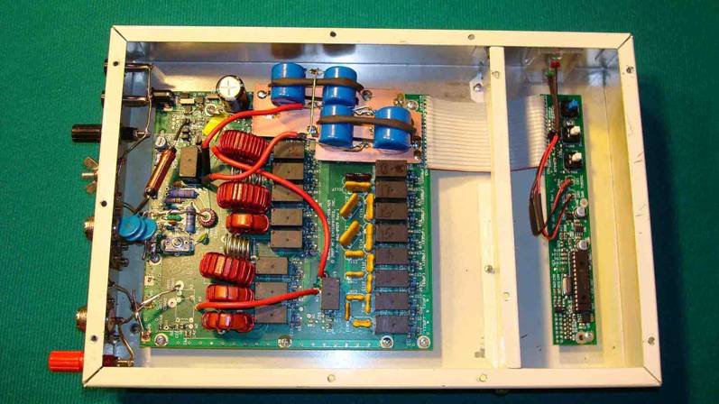
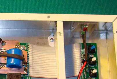
container of some sort for outdoor use. Here is a picture of the antenna base
unit with a modified MFJ 927 tuner package.
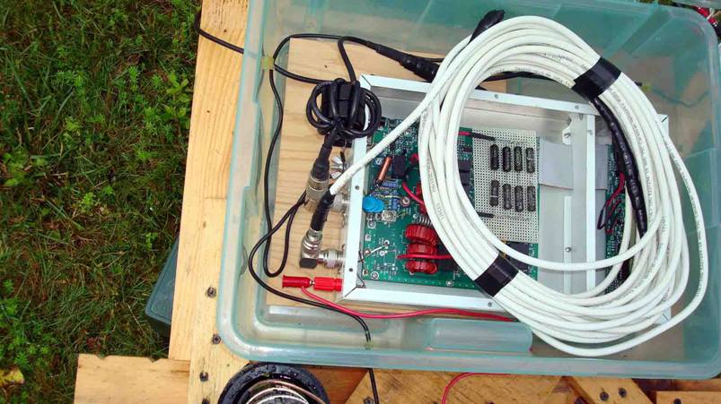
The
cover has been removed from the modified 927 package. (More on
modifications later in the story). The stub is plugged into the coax
connector which is paralleled with the red binding post antenna wire connector.
The common mode choke is on the input feed line from the transceiver.
General
Mechanical: The MFJ 927 is
mechanically well made. The SGC 239 is lighter and requires installation in a
weather proof container. No real contest here, MFJ is a good mechanical
package. Wish the cover was white, though.
Connections: MFJ 927 has very good set
of connectors underneath the SS frame. My only complaint was the height
allowance for a PL259 connector and coax is too tight, necessitating use of
coax angles. A small complaint, really. The SGC 239
has terminals for everything. I added a simple set of connectors to match the MFJ 927 setup. One good
thing is the interface control connections on the SGC 239 and external push
buttons, if you want to use them. You have to dismantle the MFJ 927 to get at it’s control buttons. One
important point.. the MFJ
uses a common earth side coax connection for input and output, the SGC does not. Pay attention to
this. That’s the reason for the (red) plastic piece I added to hold the output
connectors. The SGC does not have a built in bias T like the MFJ, so I added
one which serves as the input connector. The SGC also has a nice set of
external indicator LEDs which aid in diagnosis.
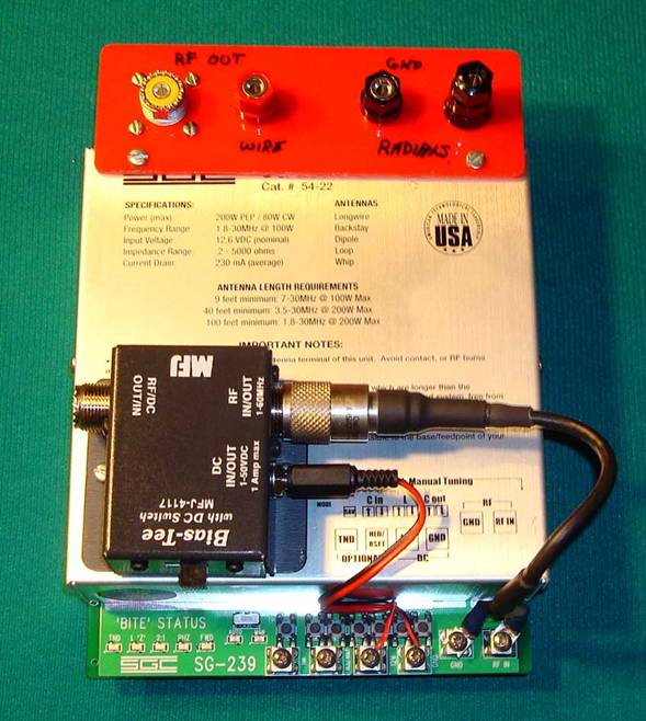
This
provides a similar set of connections to the MFJ unit, making it easy to change
the units during tests, or for operating failures during a contest.
The
banana plugs on both units are for easy attachment and experimenting with
radials.
Bypass
mode: The
MFJ is bypassed with no power. The SGC requires power on to be bypassed. In
operation, this is no problem, but when something goes wrong, I prefer the MFJ
system which bypasses in power down mode. If the SGC gets funky on you, you
have to turn it off and then on again for bypass, and there really is no easy
way to tell it to stay bypassed from then on. So, MFJ has a better system, I
think.
Coax
Bias T: I
do some weak signal, MW DXing and understand the
perils of inducing noise via power over coax schemes. However, for ham
contesting, I really do not think this is an issue. For that reason, I find the
compromise of pushing DC out to a remote tuner over the coax an acceptable
solution. The MFJ has the necessaries for this built into the tuner, and the
shipmen comes with an MFJ bias T for the transceiver end of the coax. The SGC
has no facilities for this. You either run a power wire to the unit or add the
bias T units, as I did.
Impedance
range:
The MFJ is 2 to 1400 ohms and the SGC 239 is .2 to 5000 ohms. The SGC has a broader
range and in my test vertical setup, never had a struggle with a match on any
frequency, stub or no stub in place. The MFJ unit struggled with some of the
more difficult spots, especially for 80 meter use of the 30 foot vertical
without the stub.
Board
Quality:
The MFJ unit had an alarming pattern of long wire lead protrusions on solder
side of the board that were all bent over at right angles. It’s a miracle there
were no shorts on this unit. A half hour spent straightening and properly
trimming the component leads lessened my anxiety on shorts. Soldering of
components was fine otherwise, but several wire jumpers on this until were hack
jobs. The SGC had no issues and looked very professional all the way.
Manual: The MFJ manual is in the
package and downloadable from the website. It is adequate for the task, ( barely) although it takes a few reads to get the feel of
where it is going. The 927 is the same board as used in several other units
with slightly different programming for the default “remote” features. Less
clear is the fact that you can open the unit up and use the two interior push
buttons and power switch to make this thing look like the other similar MFJ shack
mounted products. It is also very easy to knock this unit off its default
settings. A very nice feature is the built in diagnosis routines which can be
access when the unit is opened. These are explained in the manual, but it takes
a while to understand what’s going on.
The
SGC manual is the “Gold Standard” of tuner documentation! It comes as a 500 Kb
PDF document that not only explains fully the use of the tuner, but is a
document that should be used in any radio amateur course to explain how
matching works ! Really excellent
stuff. The SGC website is a little cryptic, but it’s worth a visit to
download this or other manuals or their free PDF technical documents on antenna
theory and matching. Very well done. Kudos.
Service
and Warranty:
Untested for SGC so I have no comment. MFJ has pretty good service to my mind,
if you know how to tap into it. They make extensive use of a web based trouble
ticket system which works very well. I have made use of this system many times
and have never been disappointed. MFJ is also very generous in sending you
parts if you want to try and fix your own problem, especially if you know
exactly what you want. They have never charged me for failed push buttons,
fried board components, even a blown PIC for the 927 !
This is one of the nicer aspects of dealing with MFJ, especially if you are a
good technical person yourself. The warranty claims I have made for MFJ
products were done through dealers, and always came to a happy conclusion. I
have bought several MFJ products from DX Engineering who gave exemplary service
on warranty claims with prompt shipping. MFJ also readily provided some testing
and service information not provided in the manual, through their trouble
ticket system, which resulted in a personal email with PDF documents attached.
I really appreciate this kind of service.
Price: In Canada, the SGC 239
unit is less expensive than the MFJ 927, but it does not include some
connectors and the coax bias T system, which kind of evens things out. If you
include those items, and the fancier case of the MFJ 927, it’s probably a
slightly better deal for the MFJ unit.
Operating Tests: Best to list these, in order.
1)
Previous year, fall 2011,
1st MFJ 927 tested with yard 30 foot vertical, at end of 150 foot
coax run. Unit failed after 1st hour of tests and was returned for
warranty. In these tests, power was limited in all cases to 5 watts.
2)
Replacement MFJ 927 tested
with yard vertical in spring of 2012 and on mobile antenna setup in yard for
testing before contest. 3 hour test session, no problems.
3)
During setup in QSO party
with same mobile vertical antenna setup, MFJ 927 failed. Later testing found
failed pic, several relay driver transistors and the
25 ohm precision ceramic R used in the impedance measuring circuit. This was
likely self induced ( by me) because of an error in
power delivered during the tuning function from a K3 transceiver… the lesson
here is to be exceedingly careful about sending a low power ‘tune’ signal to
these remote antenna tuners. They are easily damaged.
4)
After contest, MFJ until
was repaired by me and some changes were made to the unit to make it more use
full in this application, by my reckoning. More on this later. The unit tested
out reasonable well on the re-setup mobile antenna in my yard during over night tests. It doesn’t repeat as well as it did when
it was new, leading me to believe it still has some calibration or functional
issues, but it does work. 5 watts for tuning and 100 watts for on air tests.
5)
SGC 239 unit was purchased
and adapters added. It has been operated in over night
tests on my yard vertical and on the temporary mobile setup. Flawless
operation. Low power for tuning (5 watts) and 100 watts for on air tests.
6)
Both units were
extensively bench tested into a dummy load and a reactive OCF dipole antenna,
with the unit mounted at the shack position.
Reliability: OK, this is a tough one.
I am a little nervous about my known reliability of the MFJ 927 unit, and I
don’t have enough operating experience with the SGC 239 yet. So frankly, they
are probably evenly weighted at this point.
BUY
AGAIN Decision: Well, I would definitely buy the SGC 239
again, for this application as it worked flawlessly during the tests. My only
caveat is the bypass mode, which would require physically removing it from the
circuit if it fails.
On
the other hand, if my modified MFJ 927 stands the test of time, it may prove to
be the superior unit for remote antenna use. Frankly, when it comes down to it,
both have some minor details that need addressing before use, but I think the
real decision would be based on this bypass business and how important it was
to me. Right now, if it was critical, the MFJ 927 gets the nod, and if it
isn’t, then the SGC 239 is the one.
So,
next contest, I will test both units and take both to the contest, but probably
start with the SGC 239. With my connector setup it takes only a few minutes to
change them out.
WARNING, from the cheap seats :
If you can’t insure that tuning is consistently done at low power during
the heat of a contest, you should probably avoid using these things at all ! I
do not believe either unit is built well enough to do tuning at power over , say 50 watts for any length of time.
Here
is a picture of my favoured mobile antenna setup:
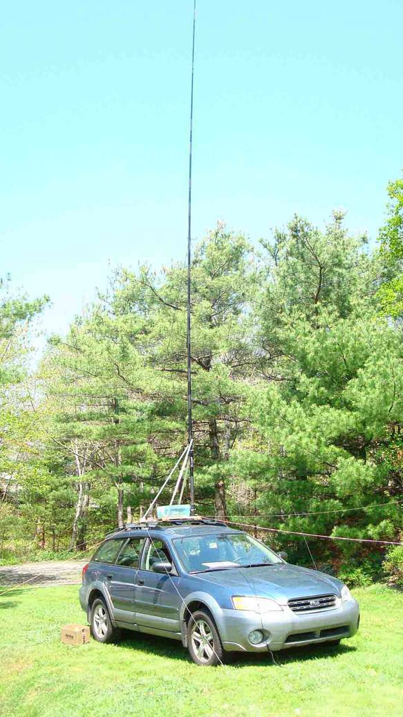
The
radials all plug into the base with banana plugs and are help out with bean bag
weights. The antenna pole is pushed up with the base on the ground and then the
whole thing is lifted to the car racks and held in place with big ty wraps. It takes about 15 minutes to setup or take down.
This looks like the way to go for any repeats of a contest or operating event
needing a mobile or portable antenna. No trees required. BTW, it was tested on
6M with no auto tuner at the base, and it worked fine with the rigs tuner.
Some ideas on the MFJ 927
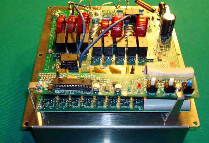
Above
is a picture of the layout in the MFJ 927 with the plastic cover removed. Below is the same unit after my repackaging and
repair efforts.
After
two failures of this device, I spent some time studying the failures and other
small inconveniences and decided to modify my unit as well as repair it. Here
are the things I changed:
1.
New aluminum case, to
isolate PIC controller from high RF fields
2.
Case painted white to stay
cooler in bright sun.
3.
Case now totally enclosed
for RF shielding
4.
Replace low wattage Caddock
ceramic resistor with 20 watts of Ohmite ‘Pulse Eater’ resistors.
5.
Add more binding posts to
facilitate radial hookup and experimentation.
6.
Modify control LEDs to be
visible from outside of case.
7.
Repair unit from previous
damage.
The
case is a standard aluminum Hammond chassis with a cover plate. The little
bulkhead allows further (not perfect) shielding for the PIC control board. The
LEDs were removed from the control board and mounted in a block of plexiglass
attached to the side of the chassis. You can now see these things from outside
while troubleshooting or monitoring operation. Very handy.
Damage
found on the boards from tuning with too much power included blowing the PIC
controller, taking out two relay driver transistors and destroying the ceramic
25 ohm resistor used in the impedance measuring bridge. This resistor is
designed to be mounted on a heatsink, and I suspect it would have survived if
there had been a small heat sink on this unit. It is mounted vertically on the
chassis and it would be easy to add a small clip on heat sink to this device…
something I would do to any new MFJ 927.
In
my case, I decided to add a higher power version of this resistor for further
experimenting. In a compromise, this also added a bit of reactance to the R leg
of this circuit.. which may
not be a good thing. For the time being I will leave it as is.
The
extra control
board shielding may not be strictly necessary, but can’t hurt either. One
problem I have not been able to fix is the SWR bridge calibration using the
built in software routine. My unit does not seem to want to easily engage the
dummy load while in the calibration stage of this routine, which requires a
little further troubleshooting, and the PIC doesn’t seem to behave in the way
expected in the instructions for this procedure. The PIC does exhibit every
other function correctly, however.
In
the end, I have a functioning unit, but it is not very repeatable. It’s
probably just me however. I plan on giving it one more set of “Factory default”
instructions and trying it with the outside vertical antenna again. It looks
like it is very close to being useable.
I
found two relay surface mount driver transistors cooked. I replaced these with
regular NPN switching transistors with leads that are soldered to the original
pads. A not too difficult repair.
The 30 foot vs 43 foot vertical antenna choice
A
little sidebar arose during all this vertical antenna and matching work.
There
is lots of talk about
how wonderful a 43 foot vertical is, compared to other vertical setups. I have
a 30 foot vertical with a base mounted switched match setup which allows it to
work very well on 80,40,30 and 15M. Not
much goodness to report on 20M, although it will load with help from the rig
tuner, leaving a high SWR on the coax feed line. It’s not a great trick for me
to add 13 feet to the top of this antenna, but I figured I better look at what
that might get me before going to the effort.
BTW, there is a very good analysis of 43 foot antennas at http://www.hamradio.me/antennas/answer-to-everything-43-feet-antenna.html
and http://www.hamradio.me/interests/43-foot/ His conclusions seem to match mine.
The
problem with the 30 foot vertical is 80 and 20M. I don’t worry much about the
high bands as I have a 2 element Steppir yagi available which performs very well 20M and up. But,
it’s always nice to have a selection of antennas to utilize for DX hunting and
contests.
So,
how great is the 43 foot antenna ? Well, it looks like
the only real advantage is the lower reactance at the feedpoint,
making matching an easier go. But do you actually gain anything
? EZNEC gives us a few good hints. Look at the following comparison
sheet I made up with gains of the two verticals over medium to poor ground
(that’s me !)
|
Side by Side comparison of 31 ft and 43 ft vertical |
|||||||
|
5/7/2012 Check means "Winner" |
|||||||
|
Item |
31 feet |
43 feet |
Note |
31 ft |
43 ft |
|
|
|
Gain at 160 |
√ |
* |
0.25 |
0.23 |
|||
|
Gain at 80 |
√ |
|
-0.43 |
-0.45 |
|||
|
Gain at 40 |
√ |
|
-0.64 |
-0.47 |
|
||
|
Gain at 30 |
|
√ |
|
|
-0.41 |
0.19 |
|
|
Gain at 20 |
|
√ |
*** |
|
0.29 |
2.04 |
|
|
Gain at 17 |
√ |
1 |
2 |
0.65 |
|||
|
Gain at 15 |
√ |
2 |
2.28 |
-0.51 |
|||
|
Gain at 12 |
|
√ |
3 |
|
-0.29 |
1.18 |
|
|
Gain at 10 |
√ |
|
4 |
-0.74 |
-2.31 |
||
|
Totals |
2.31 |
0.55 |
|||||
|
Score |
Score |
||||||
|
Matching needs |
√ |
√ |
5 |
5 |
3 |
||
|
Installation ease |
√ |
6 |
5 |
3 |
|||
|
Totals: |
|
12.31 |
6.55 |
:Hybrid |
|||
|
Point Scoring system: |
1 to 5 |
||||||
|
Very Good |
5 |
||||||
|
N/A |
0 |
||||||
|
* Notes: 1 |
43 has
gain of 4 dBi at 40 deg |
||||||
|
2 |
43 has
gain of 3.7 dBi at 40 deg |
||||||
|
3 |
Both
have 4.4 dBi at 40 deg |
||||||
|
4 |
Both
have over 4 dBi at 40 to 50 deg. |
||||||
|
5 |
Auto
tuner for 43, existing switched passive for 31 |
||||||
|
6 |
31 in
place, 43 needs 13 foot extension, new guys. |
||||||
|
* |
Gains
based on EZNEC model over poor ground |
||||||
|
*** |
Even
though 43 much better 20M vertical,
have a Steppir beam for 20M |
||||||
The conclusion is that the antenna can give a
.6 dB relative gain on 30M and a 1.7 dB relative gain on 20M. Consider that an S unit is around 6
dB, and you can see that this antenna is not going to change very much. It may
be worth doing to get a better 20M signal leaving the antenna, but I already
have a yagi for that band, so it’s hardly worth
doing. It looks to me like there is
little to be gained by doing the work to add 13 feet, the same as there is
little to be gained by adding an auto tuner at the base, compared to my
existing ultra-reliable switched matching unit. (There is some description of
this unit in other articles on this website, and a picture of the matching unit
in the picture sidebar) For 15 and up, the 43 footer is actually quite poor for
low angle work of any sort.. it
wants to push most of the radiation out at high take off angles.
Considering
the needs for increased guying and a little more handling work, it’s not on my
antenna upgrade list.
I
hope this vertical information is useful to some of you folks making antenna
decisions in the near future.
Jeff VE1ZAC