Phase
Controlled Receiving Array For QRP Low Band Fox Hunting Use And Small Lots
Jeff VE1ZAC
I enjoy a good
radio challenge, like many other amateurs. But one that exerts particular adversity
on the participants is the QRP fox hunt series that envelops the winter months
here in
This was my third
year of fox hunting with this group. There are some regional issues which
affect my efforts as well as the usual low sunspot flux numbers which affect
everybody lately. The hunts occur at 0100 to 0230 UTC. Let’s look at what that
means to me in North East, as compared with someone in the middle of the
continent. At my QTH, 40 and 80 start to
pickup just before local sundown and aren’t in bad shape to about 2300,
typically. Propagation may be off but signal to noise ratios aren’t too bad.
The first signals appearing will be from the East on 40M and the South East on
80M. The problems for me really start as 0000 rolls around. The noise levels
start climbing on both bands, but especially on 40M. This noise makes it almost
impossible to pick out QRP signals which are below the average noise levels on
my OCF dipole and vertical antennas. The first two years produced dismal
results for me in the hunts. The middle of the continent does a little better
since 0100 corresponds to this earlier sundown period with less noise. The
noise phenomenon does seem to happen right across the continent however. It
also seems worse the more North you are. ( anecdotal evidence).
Propagation
Noise reduction tools
I have
experimented with two means to aid my fox hunting efforts. Last year I brought
some directionality to my 40M vertical with a director wire mounted near the
vertical element. This helped a little, but not enough to change my results much.
I still had that cloud of noise descending on me at the usual time. The
director element did produce a few more contacts, but that might also be due to
increasing my ERP in the West direction.
Last summer I
started a major rethink of the problem. Typical Beverage antennas are not
available to me. I live in an urban area and can just barely get an 80M wire
stretched out. In one case I did try a 200 foot BOG (Beverage on Ground)
antenna, and it worked wonderfully on 160M, but not so great on 80 and 40. What
I need is a way to decrease that noise signal coming from the East by more than
a few dB that you get from a director or reflector. I want 3 or 4 S units of
noise reduction, maybe -24 dB. If I could do that, the very weak QRP signals
should show with an increased signal to noise ratio, which is what I really
want.
How to get -24
dB? I have previously studied and
implemented techniques from Victor Misek’s book “The Beverage Antenna Handbook”
(Available from www.radiobooks.com) I implemented
several experimental models of his Steerable Wave Antennas successfully,
but mostly for 160M. I built one of the Misek designed phasers, which worked
well, but I still wanted a bigger performance increase for 80 and 40. (You can
follow along with my experiments on my website)
The “Lankford
Files”
During my
research, I looked into efforts that some of the keener SWL DXers have been
using and came across Dallas Lankford.
My phase 1
experiment
Phase one involved
experimenting with some of my existing systems to see how this steerable null
concept would work on the fox hunts.
I was particularly
interested in
Phase 2
experiments
OK.. I am
convinced that this null steering technique is a winner.
Here is a reprint
of the MicroSWA from Misek’s book. I pretty much followed this version and used
RG6 feedlines.
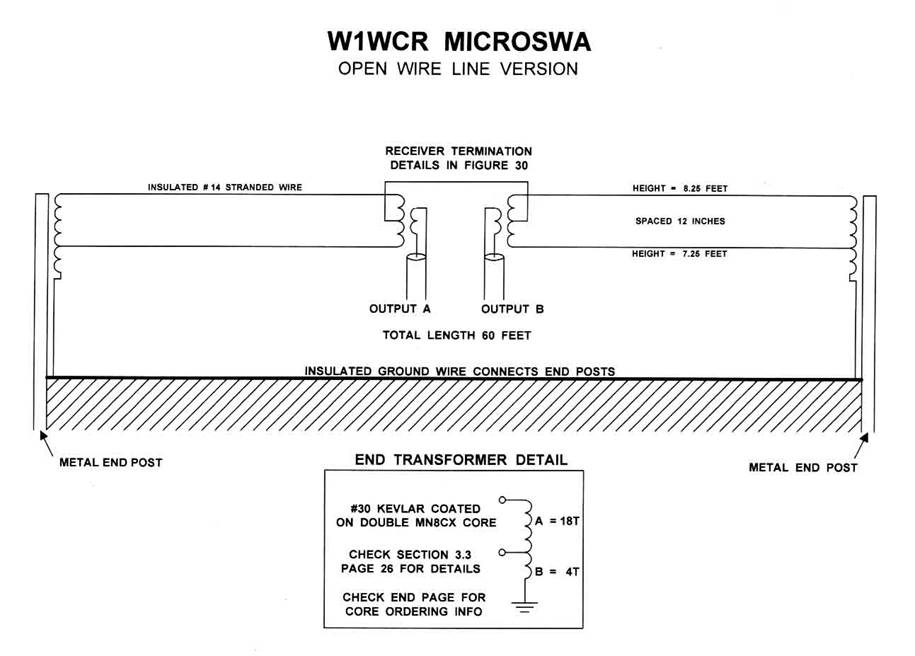
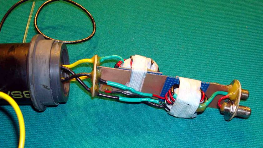
The Faraday
shielded primaries were made with RG174. I used larger -75 ferrite cores, as I
had a bunch around. Overkill, I know, but I won’t have to worry about
saturating them. I wound the cores with fiberglass tape to provide insulation
and the RG174 was fairly easy to use with the Faraday shield method. The
transformers are enclosed in ABS plastic pipe housings. I am proud of my simple
wire termination methods. You can see how I passed 300 lb. test monofilament
trawl line through the housings and crimped an aluminum joiner on the inside to
anchor them.
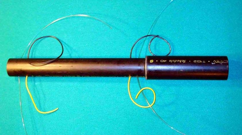
My antenna wire (
which is unusual surplus F18 aircraft cable with Kapton insulation) is then
crimped to the monofilament. The two ends are mounted on aluminum poles to
shield the vertical piece of the ground wire and the entire system is stayed
with a pair of monofilament guys at each end. One of these guys has a bungee
cord element, which is all that is needed to keep the system taught through
temperature changes and winds. A door spring also works well for this job, and
I may replace the bungee cord this summer. I have found bungee’s don’t last
very long in our climate. The springs last forever. I took pictures before
spray painting all the parts with flat black. I have found that flat black is
the best camouflage for antenna poles and components. After painting some of my
antenna supports, neighbours have asked me why I took them down, and were very
surprised when I pointed to them still standing !
Not shown, but
there is an aluminum sleeve shielding the two feedline transformers in the center
unit.
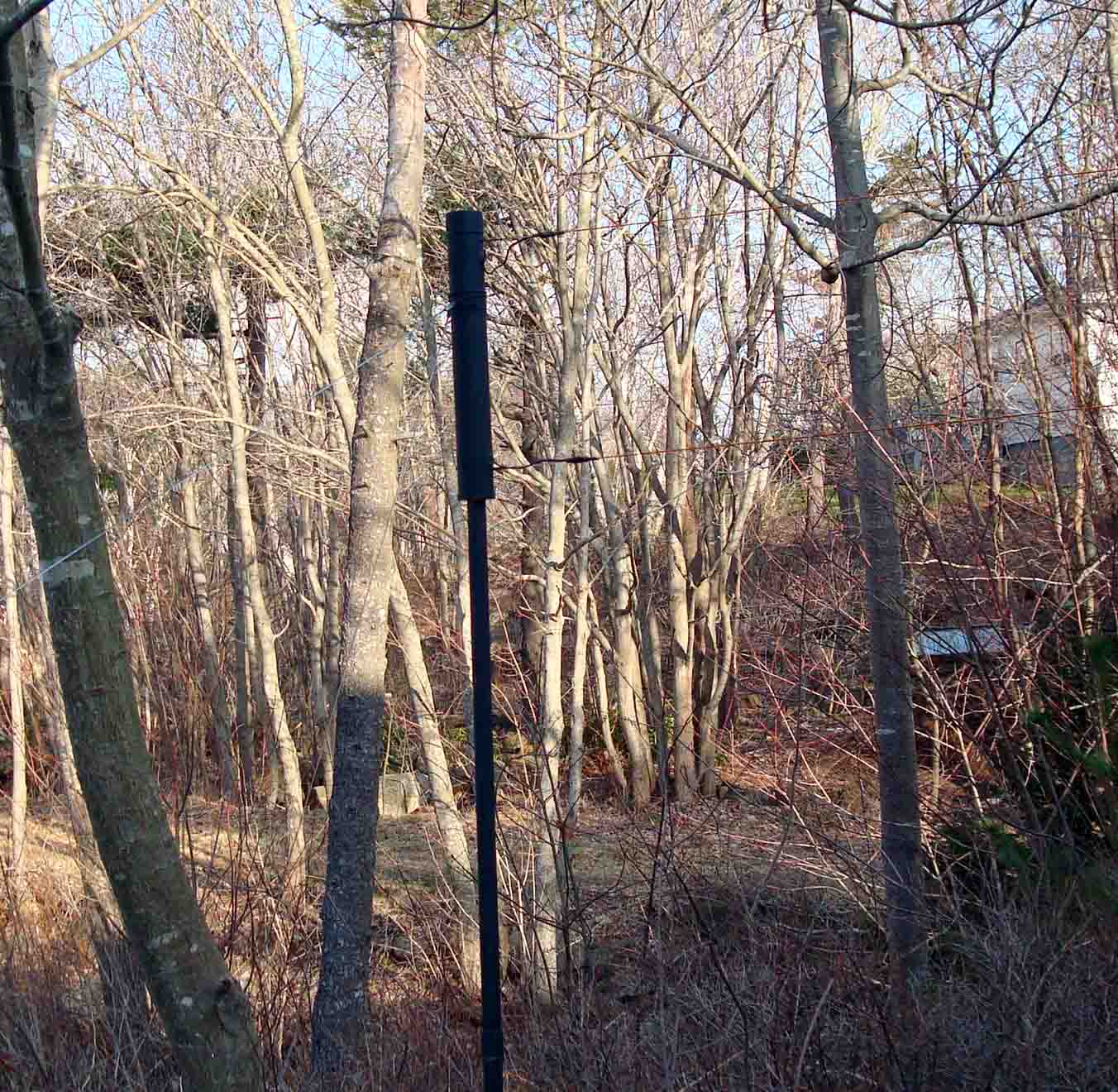
The housings and
antenna erected, before painting black. They are about 6 feet off the ground.
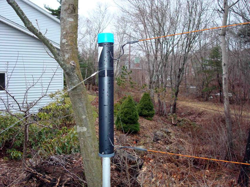
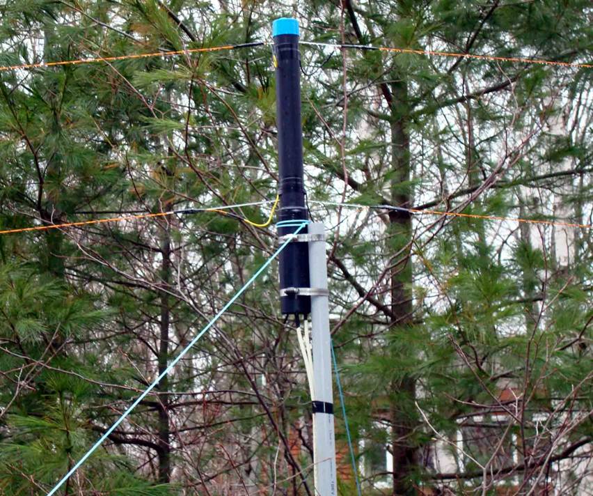
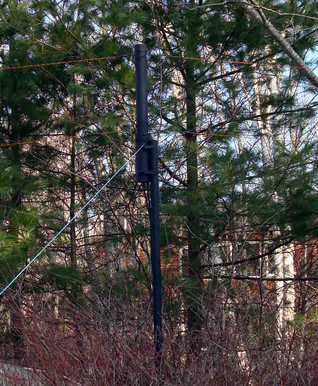
Here they are after painting flat black. They
blend in much better !
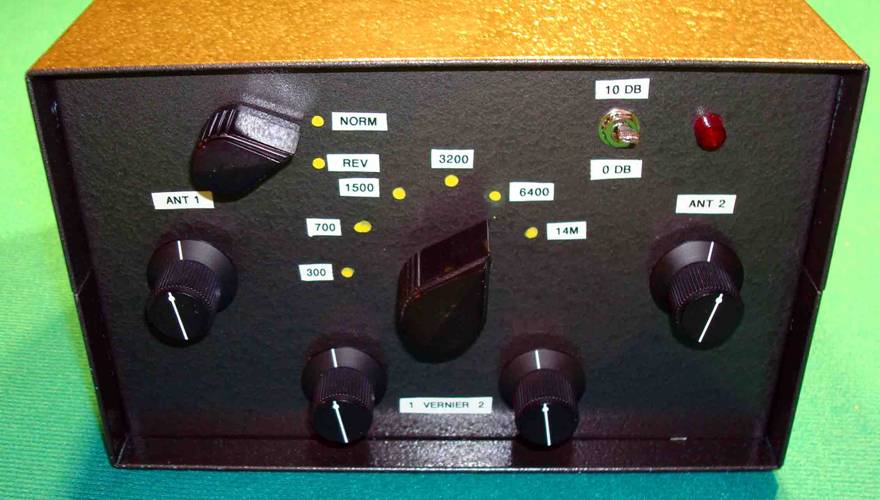
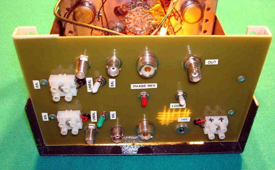
Next is the new Lankford style phase control
box.
The front panel
controls are identical to the Lankford specifications. I have included the 10
dB preamp ( might actually be 11 dB) in the same box and it has a front panel
control. Power is taken from my IC7700 acc power output. The two bottom knobs
are on vernier controls. They didn’t turn out to be all that necessary. This
unit can be used up to 30 MHz, bit is mainly for the low bands. High angle RF
doesn’t null very well, which is pretty much everything at higher frequencies.
I decided the back
should handle any transmission line I might throw at it. Includes balanced and
unbalanced lines, and even a terminal block for power supplies that don’t have
the right kind of plug on them ( Field Day, anyone ?)
You can just see
the front panel at top. The inductors and caps are mounted on the band switch
directly.
Inside you can see
the new push-pull Norton amplifier. I made a board with Eagle Cad and my
Sherline mill as I intend on making a few more of these fabulous RF pre amps.
The IC7700 uses one of these in it’s pre amp stage. Mine use 2N5109’s.
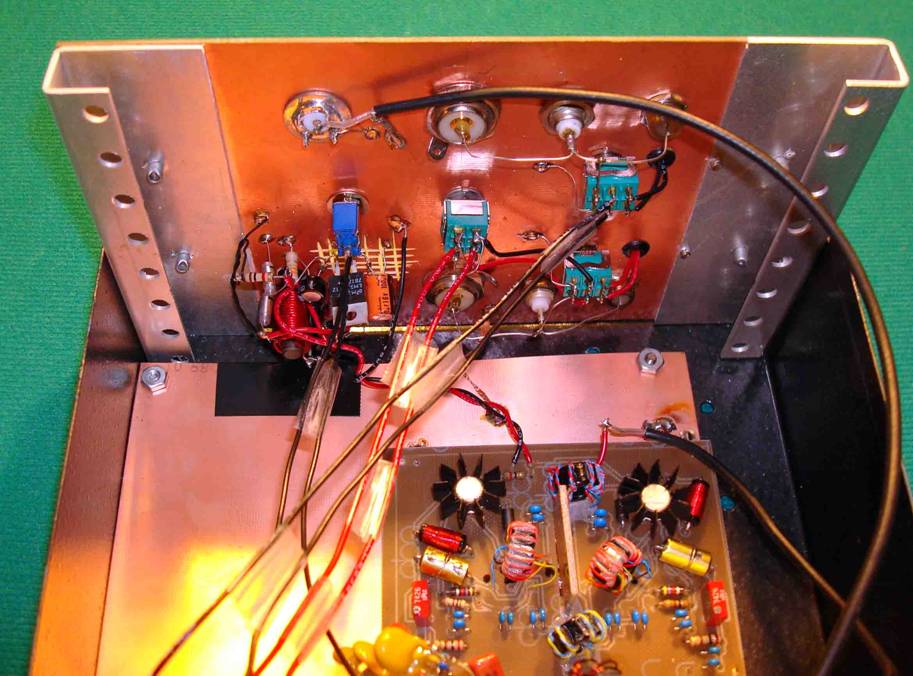
At the lower left
on the back panel is a power conditioner… it has a PTC type fuse, reverse
blocking diode, choke filters and a 12 volt 3 terminal regulator. NO power line
RF welcome here! Copper clad PC board is used liberally through out. Note the
lash up parallel lines made from hookup wire and scotch tape, (an act of
desperation). Flex braid joins the two panels, floor and case together. This unit
sits on feet allowing a slight tilt, and just to the right of the IC7700 in the
shack. Very convenient.
How does it
work ?
Not shown is a
small switch for two sets of parallel feed lines that enter the back of the
unit. I can switch between the two verticals or the MicroSWA. I have had this
unit together for a few weeks now and have been tuning everything I can find
for a good test almost every day. The results favour the Micro SWA so far.
Also, Lankford claims that the MicroSWA has a single 360 degree steerable null.
That is confirmed by my EZNEC efforts. It produces wonderful nulls as I had
before, but there is more range and a nicer feel to the unit. I took Lankfords
advice and fussed over the pots used in the unit. His recommended source at www.tedss.com is an excellent tip. I got the 4
pole 6 position switch there as well. I am glad I did, as these pots are
superior to the ones I used in my Misek phaser.
Why the fussing
over the Norton amp, you might ask ? These amps are capable of producing up to
95 dBm or more at the 3rd order intercept. In the presence of strong
signals, this is what you want. No other design of RF amplifier is as capable,
according to experts. That means very little degradation of your weak signals
in the busy ham bands.
Last night, April
16, was the last night of the low band fox hunts for the year. The Micro SWA
was up to the job and dealt with the usual difficult noise quite nicely. I do not believe I could have worked as many
QRP stations without it. Several times I switched to the transmit antennas and
lost the QRP signals I was copying handily on the MicroSWA.
I will be using
this system extensively this year on 160,80 and 40M. I can’t wait for next
winter to see how the fox hunts go with this improved receive antenna system.