Pennant Loop
adventures
Jeff VE1ZAC
Sept 09
Antenna
stimulation
One nice August
morning I was outside surveying the side of my property that contains rocks,
blueberry bushes, assorted ‘wild’ trees, alders and some of my collection of
antennas. While sipping a coffee, I
noticed a maple tree that had an unused halyard in it. Hmmmm… not only that,
but there was an unused RG213 lying at its foot that came into the shack
through a lightening arrestor, nice common mode choke and an antenna switch. Unused,
that word has implications! I wondered
what I could do with these support items to contribute to my ever pressing low
band antenna needs. What about a Pennant
antenna? Indeed, there was another sapling about 35 feet away. The typical
Pennant needs about 30 feet of ground space. This might work.
Layout ideas
I would love to
experiment with a terminated loop, and the Pennant would just fit in this
space. My needs for a low band directional antenna are largely geared toward
the SW from Halifax to aid in low band fox hunting, a few QSO parties and a
couple of 160M events. Turns out, the line for the existing supports would
point the antenna null towards the Atlantic NE (desired) and towards my main
low band transmit antenna. This is also desired to minimize the affect of the
close antennas to the Pennant loop.
Perfect. A Pennant it is.
Modeling
The Pennant is
known for being less ground dependant than some other loops, notably the K9AY.
I don’t think this is a big factor in my location as my ground consists mostly
of rocks. It’s poor no matter what. EZNEC shows a very nice cardioid pattern
when the antenna is terminated with 800 ohms at the small end. In fact, this
pattern really didn’t change much when the freq varied from 1 to 10 MHz and the
low point of the antenna varied from 5 to 15 feet from the ground. That seems
too good to be true? I could easily use
the higher elevation, so that’s where the antenna wound up. Given a choice, the
antenna is probably going to be a little quieter the higher you can get it.
Design
I found a series
of nice articles by Mark Conelly: (http://home.comcast.net/~markwa1ion/exaol2/pennant.htm)
Plus there is a pile of articles and notes from the original experimenters and other notable antenna folks on http://www.angelfire.com/md/k3ky/page37.html and other sites. It’s worth wandering through these articles and notes. I elected to go with the compact 14 foot by 30 foot model which just fit in my serendipitous location. I also decided to go whole hog and install the remote controlled variable termination based on a Vactrol opto coupler as described in Mark’s article. Mark’s circuit seemed fine to me with a few small changes. I changed the 1n4003 clamp diodes to 3 amp fast recover diodes (FRD’s) to aid in protection duties. Plus, the transformer was wound on a 50 mix core of a slightly larger size. ( Steward epoxy insulated ferrite toroids which are sold by Digi-Key. The Steward part number 35T0501-10H (AL = 3659, Digi-Key catalog number 240-2524-ND)
No saturation
problems there. Less windings are needed to match a
coax to the 800 ohm antenna Z as well. (5 and 18 turns do the trick, when
tested with an analyzer and an 800 ohm resistor). I also decided to build a control box with a
10 turn pot, a plug in current monitor to aid adjustments and a built in 12 dB
push pull CBTF Norton RF amp a la Dallas Lankford. I have built several of
these amps with really great results. (CBTF means common base transformer
feedback) http://www.kongsfjord.no/dl/dl.htm
I highly recommend
them for your loop projects or as feedline isolators.
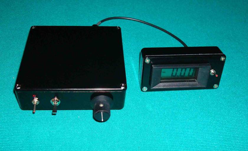
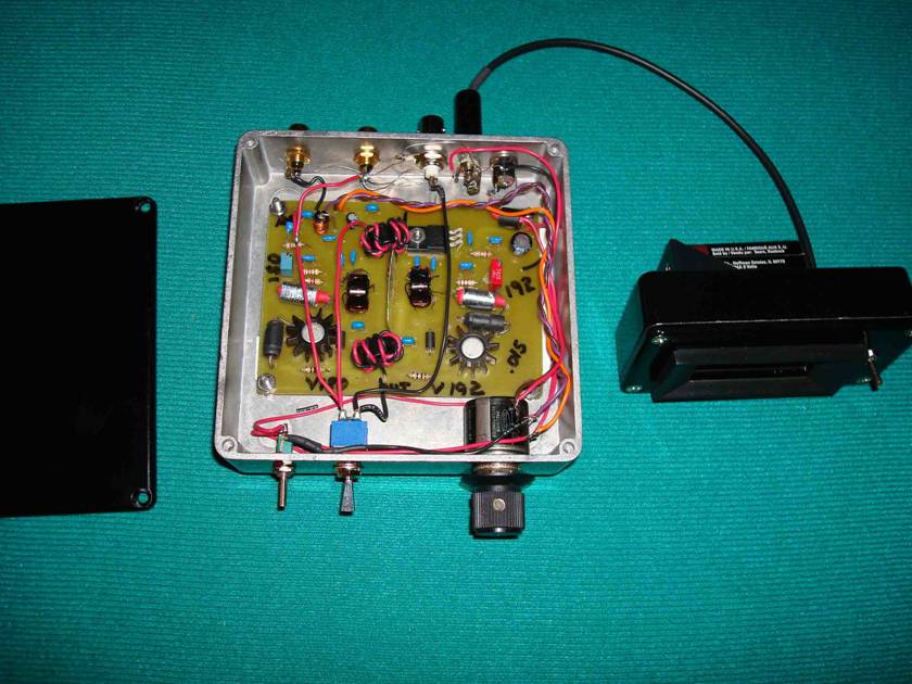
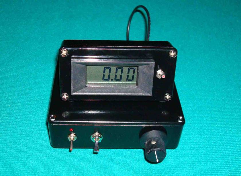
Pictures
Here is the control
box, and the method I use to build inline weather proof circuits in my
antennas. The termination end is shown. The 300 lb. mono filament support line
goes right through the case and out the ends. I only glue one cap end and tape
wrap the other end to allow disassembly if needed. The tubes are PVC vacuum pipe, and the caps
are made on a lathe from PVC. I kind of suspect this antenna will be up and
down a few times for experiments and maintenance, so I used pulleys, springs
and shock cords to suspend everything. No picture of the feed point, but it is
similar and vertically oriented.
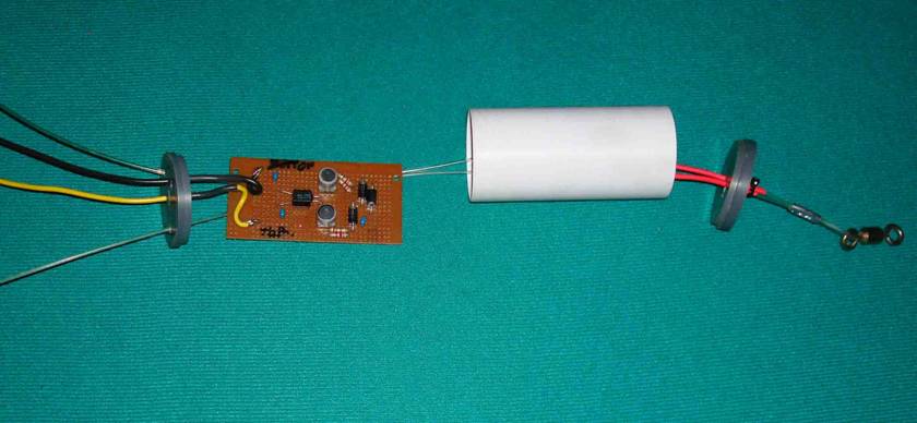
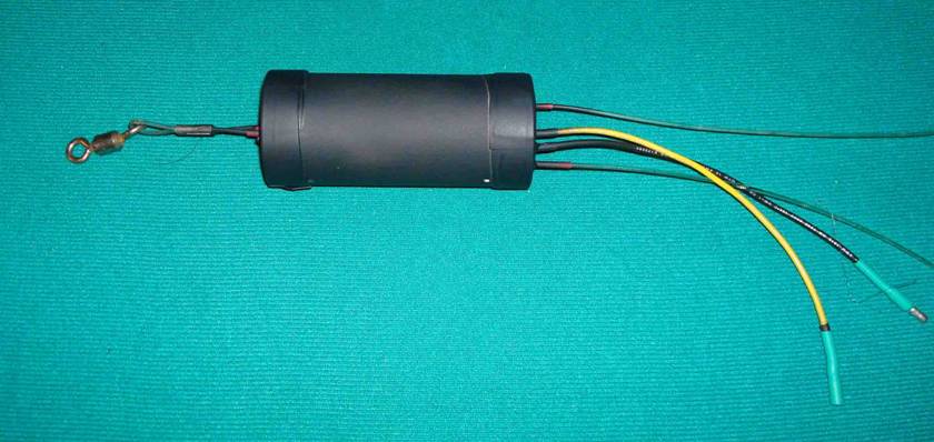
I used a plug and
socket on the termination end so I could try out a fixed resistor easily as a
termination.
The digital
display is a 2 volt LCD voltmeter looking across a 10 ohm resistor in series
with the power line going to the remote control network. The RF amp can be
switched in and out.
Measurements
Before taking the unit
outside for mounting, I hooked it all up in the shop and measured the
resistance of the Vactrol device at 1 mA increments of current. This way I will
know exactly what the termination resistance will be, and have a way to
checkout the health of the remote devices from inside the shack. Incidentally,
the clamp diodes are forward biased and conducting all the time. The current
leg through the diodes is about 6 times the current through the LED of the
Vactrol. This is fine, but you would not necessarily know that the LED had
burnt out without bringing the termination unit indoors and opening it up. Actually, I am less worried about that than
destroying the photo sensitive CDS device on the other side of the Vactrol.
This circuit is capacitive coupled at several points, but high RF currents
could destroy this unit. I have no experience with this yet, and recognize it
could be a weak point. On the plus side, this is a very small loop, very
inefficient and should have small currents and voltages on it.
Comparisons
The first night I
had the antenna up, I plugged an 800 ohm resistor in at the termination end and
had a listen around the bands. It worked very much a
advertised. I am able to switch this antenna and a short SWA(
Steerable wave antenna, Mizek design) into my IC7700
receive port. As expected, stations from
Next, I installed
the remote control termination and had another listen around the bands. My
modeling efforts showed the best nulls were obtained with the termination R
around 800 ohms. Much above or below this the antenna becomes quite a bit more
omni directional. I can confirm this happens. The nulls are not as deep or as
variable as I can get from the SWA and phase control setup, but they are
obvious. My feedline location is not entirely satisfactory and may soften the nulls
that are available from this antenna. Note that I installed lots of feed line
chokes (snap on ferrites) on my feedline to break up the shield length, as
recommended.
Comment
After listening to
both the fixed resistor and the remote controlled Vactrol termination, I am not
sure I really need the remote control device. I think I would be happy with the
fixed resistor. If I have any serious maintenance issues, that is what this
antenna may wind up with. In the meantime, I can experiment to my hearts content
and keep notes on the termination R that works the best. This is a very quiet
low band antenna that is easy to build and works as advertised. This one is a
winner for low band receiving at any QTH with a small yard.