Part 3- some
notes on the parasitically enhanced vertical
Jeff VE1ZAC
Sept 2007
I
have mentioned several times that I have a less than ideal location for RF
activities. I am in the city of
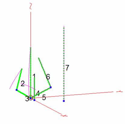
Here is the model with the steel post and windom feedline in play with 30M currents. You can see there is little effect on the antenna’s current distributions.
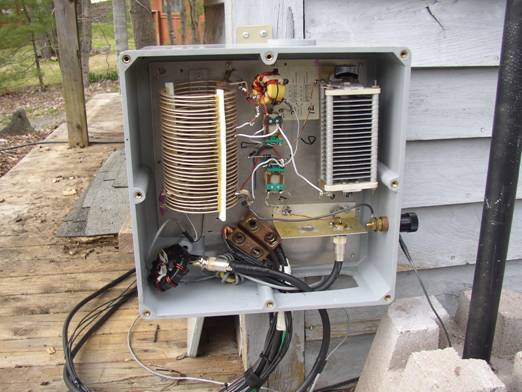
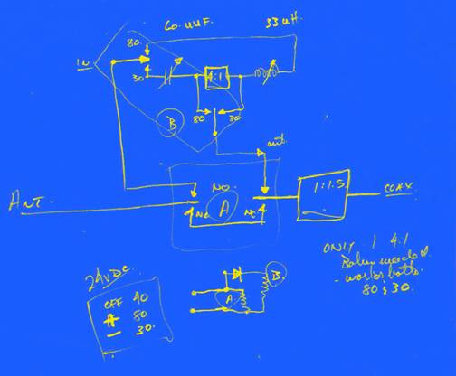
Here is the matching device at the base of my antenna, and a sketch of the matching circuit I use for 80,40 and 30M. The 1:1 UNUN is now a switchable 4:1 UNUN.
Now for the dimension sketch:
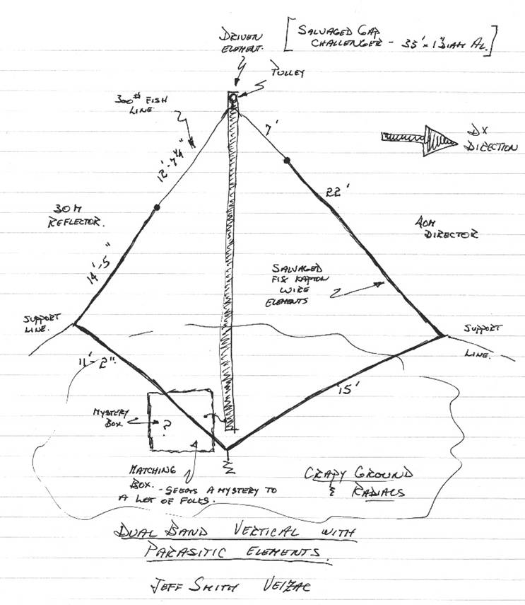
Note: these dimensions are particularly dependent on my antenna and location. If you try this, without modeling, allow adjustments in the geometry and monitor the feedpoint impedance for a good “Dip” where the Yagi effect develops. Personally, I think it’s easier to model the thing and then cut wire. Caveat Emptor.
Working
the ether : Last night the 3B7C
operation was on in full swing. I monitored for a while. 20M was weak but
possibly doable with the Stepir beam, 30M and 40M
were pretty fair and 80M was pretty fair.
The vertical was the best listening antenna for 30 and 40. The windoms brought up a lot more noise and a lot more hams in
the
Kept trying 20M and 80M with other antennas, power ( my little homebrew amp can do up to 600 watts out.) and no power.. no luck. Well, looks like Mr. Vertical array was the right thing for the job !
“To infinity…. ….And beyond ! “ ( Buzz Lightyear)