UPDATED May, 2010
Part 3 of
the Second Receiver for an IC7700
A
compensated splitter for feeding a software receiver
Jeff VE1ZAC
Device
Communications
I have been having
lots of fun getting the SDR-IQ running in conjunction with my IC7700 and DXLab
software. The coms with the SDR, the
IC7700 and the PC have been sorted out thanks to a tip by another user. The
IC7700 has two CI-V channels… one via a DB9 RS232 style port and the other via
the CAT line that ICOM and other manufacturers use to hook various RF gadgets
together. The SDR talks to the rig via its own CI-V adapter to the IC7700 and
the PC goes direct to the IC7700 via the RS232 port. Both ports are transparent
as far as commands go. This combination has been working perfectly for several
weeks. It allows any of the modes of the SDR to be controlled by the IC7700
and/or the DX Lab suite applications via Commander.
Operating modes
I am very enamored
with the spectrum display that follows my rig tuning and allows a really
beautiful look at signals close by or anywhere else, for that matter. You can
look else where for band openings in other bands than the one you are parked
in. or hunt out pile up openings. It’s great! If you turn on the demodulators
in the software, you can actually listen and track one or two signals as you
move the main rig around the band.
CWSkimmer
WARNING
! Do not try this if
you are prone to addictions! (hah hah) Seriously, if you haven’t tried this amazing piece
of software, I suggest you head on over to the DXAtlas site and download this
software. It is free to sue for 30 days. After just 5 days, I am convinced it
is a bargain if you register. ($75 to Alex at DXAtlas, Afreet Software). This software
works with ordinary sound cards and can scan the audio pass band of the
receiver you feed it with, but frankly, this is like walking compared with an
F18! If you have a software receiver, you really want to try this out. Skimmer
grabs the full command set of the SDR-IQ (and other SDRs as well) and operates
it as a standalone receiver. Great, you say, so what? Well, the ‘what’ is that
Skimmer actually ‘Operates’ for you and decodes every CW signal it can latch
onto in the SDR pass band. In SDR-IQ mode, this is between 50 and 190 kHz. Alex
has implemented a decoding scheme using Bayesian statistics and filtering. Pretty sophisticated stuff. And it works !
After a few minutes of listening, Skimmer begins to populate a database with
call signs and other useful DX features. It looks for things like a ‘599’ being
transmitted, to help you locate the station in a pile up that the DX station is
working. After 20 or 30 minutes on 20M CW, I have seen the database grow to
over 100 entries.
And there is more.
There is a built in telnet feature which if turned on, allows you to hook up to
Skimmer as a spot source. All of its QSOs and data are available to your DX
software and full inter action with your transceiver. I have been using this
for a few days with DXLab, and it works perfectly. It’s pretty amazing to have
this thing sitting there listening and reporting on stations for you… just like
a second op. What a great assistant! (I
can see why there is a move to declare Skimmer use as assisted contest
operating.)
The antenna
splitter with a gain stage
My trial splitter
device as reported in Part 1 works very well. It has about 3 dB losses though
and I occasionally find that a bit annoying, especially on the higher bands.
Further, since I know longer have any interest in operating a second
transceiver as a second receiver, I don’t need all the bits to prevent
accidental transmitter input. So, time to toss the experimental unit and build
a new one. This time I will put it in a proper box on top of the rig, include
some switches to allow easy switching to another receive only antenna, and
include a wide dynamic range gain stage to compensate for the splitter losses.
This will have a switch to defeat the gain stage, if not needed. (My splitter
ideas were gleaned from http://www.qrp.pops.net/swl-ant-split.asp
) I have swept this unit with a spectrum analyzer and tracking generator right
up to 60 MHZ with satisfactory performance.
For a gain stage,
I wound up back at the same site and found a wonderful broadband gain stage
with low noise transformer feedback. See http://www.qrp.pops.net/preamp.asp
and check out the broad band Norton design using a 2N5109. (
2N5109s are available from Mouser Electronics http://ca.mouser.com/Home.aspx . I got a handful a few years ago for just
this kind of use) I setup my amp for about 6 dB gain. In practice, it just
seems to push the splitter transformer losses back to 0 DB. There is potential
for increased IMD issues with some gain stages. This particular one is set at a
very low gain, has a very low noise factor and can be switched out when needed.
That should take care of any issues, if they arise.
Construction
I use Eagle Cad
(the free version) to make small circuit boards with my little Sherline CNC mill. There is a free G-Code output module
available via the Yahoo PCB-GCode group. This works
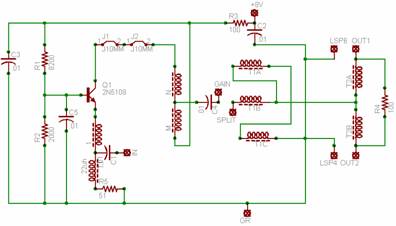
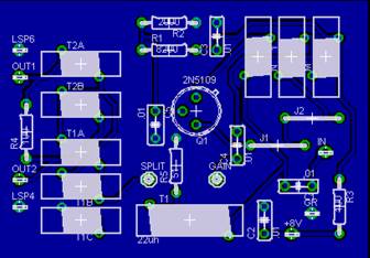
very well. Here is the schematic and board layout for a single sided board.
 ( If anyone wants my Eagle Cad files or the G-Code outputs, email
me and I will send them to you) My board includes the splitter transformers and
pads to allow external switch connections.
( If anyone wants my Eagle Cad files or the G-Code outputs, email
me and I will send them to you) My board includes the splitter transformers and
pads to allow external switch connections.
Jumpers J1 and J2
are shown to allow ferrite beads to be installed on the collector lead, as
shown. T1 and T2 are the splitter transformers, and 1,N,and
M are three windings on a binocular ferrite core for the amplifier. My power is
taken from the 8V regulated pin on the ACC2 plug on the IC7700.
Here is a board
layout view and a shot of my little homebrew CNC setup. I use Mach3 on an old
laptop to run the system. The modified PC case has the stepper driver inside
and uses the PC power supply. Note the large red ‘Panic’ button on the desk. I
have not had to use it yet !


I engage or
disengage the splitter from the IC7700 antenna controls. This unit takes care
of all the features needed to dress up using an SDR with the IC7700. ( I know, the labels are on crooked) Actually, it would work
the same for just about any transceiver setup. After seeing how well these
standalone SDRs work, there doesn’t seem to be any real need to have one look
at limited spectrum from an IF port on a transceiver. Especially
when you can range around the entire HF band directly with the SDR.
May, 2010 UPDATE on this
splitter: There was an inherent problem with the gain
stage used in this splitter. The amplifier dies below 1.8 MHz. I occasionally like to tune around in the BCB
and LF bands and this means I would have to live with the approximate
I had intended to
replace the preamp in the splitter with one of these and finally got around to
it. The swept loss of the splitter is
about 5 to 6 dB over the range of 50 kHz to 35 MHz. I elected to use a 10 dB gain preamp with a 4
db pad at the output to increase it’s isolation
characteristics. The unit swept at + .5 dB across the entire range as a result.
Essentially, I plan on leaving the splitter in place as a default arrangement.
Here is a shot of
a pair of the units. One is 10 dB, the other about 18 dB for the phased
vertical project. These are push pull maps with 2N5109’s , homemade heat
sinks and the transformer feedback promoted in the Norton original article and
by Dallas Lankford in his website postings . ( Link
available on this website front page).
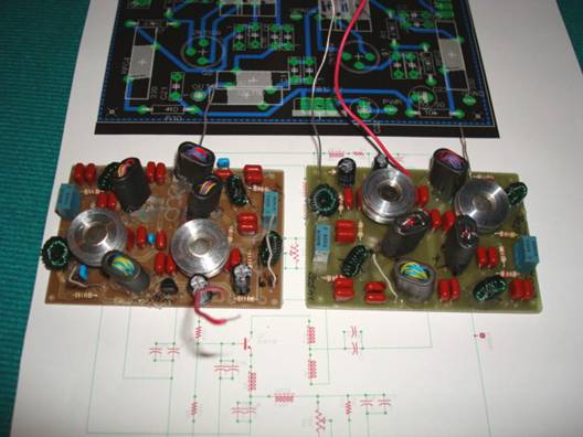
On some of the units
I used 75 mix ferrite toroids to make the input, output and feedback
transformers to insure a very broad bandwidth. On these particular units I used
73 mix ferrite binocular cores with no apparent lack of frequency range.
Windings are a combination of #30 Kynar wire, magnet
wire and a few stray bits of solid hookup wire. I tested the finished amp from
50 KHz to 30 MHz with no dips apparent anywhere. The pairs of .1 uFd
capacitors are to provide
low ESR at the LF beacon band, and up.
If you need very high
quality preamps for splitters or receive antenna projects, I highly recommend these preamps. If you don’t want to
build them, you can buy them from KIWA.
I have these
preamps built into this splitter project, a K9AY gain stage, as well as three of
them inside the phase control for the short vertical phased array.
A Postscript: I discovered that DXLab and Commander
like to running, before you engage CW Skimmer. For some reason, there are com
port conflicts if done the other way around. I will look into this when the
opportunity arises, but in the meantime, the order of starting up is easy to
deal with.
I hope you have as
much fun with an SDR as I have. A truly useful addition to any shack.