The Allure
of Top Band… and Doing Something About It !
Or.. the Birth of the “WindoVert”
Jeff Smith
VE1ZAC
Bottom of the
sunspot cycle and need a DX challenge? It always comes down to this…. Top band ! It has
propagation characteristics all it’s own, it’s elusive
and maddening. It’s like an itch that has to be scratched. Plus, 160M means the half wave length is a
whopping 262 feet !
When you live in an urban area, that is a
monstrous number. 262 feet for a dipole ! 130 feet straight up for a vertical or the proper height
for a wire. How on earth can you deal
with this from a city lot ?
Turns out, there
are plenty of ways, but they are all “Compromises”. Huge surprise, eh ?
And yet again, antenna modeling with EZNEC comes to the rescue.
Height is
really the key factor for 160M, and next to that is horizontal space. I say height is the priority because even if
you want to use a shortened horizontal antenna, you still have to get it up
pretty high if you want to do anything other than warm clouds. So… height, yup,
we gotta get up there somehow. To compound the problem, height has some serious
issues of exponentially escalating costs and risks.
Well, after the
hurricane that hit
However, while
this antenna works very well at 80M, it is still less than optimum height for
good low angle radiation, which is why I also have a short 80M vertical to use
when needed. On 40M and above, the Windom works very very well. I use it for a
horizontal antenna on all bands 80M and up and have verticals to work with for
80,40 and 30M, and 2 element Steppir
beam for 20M and up. A nice collection of antennas for DXing
with proven results. I operate QRP fairly often with decent results.
When needed I can bring an extra 600 watts to the frontline with a little home
made amp. All this seems to work very well for me. If
I can hear DX, I can usually work it.
(Note: A
Except,
of course, 160M. ……………..Sigh……………….. This one is a
problem. So, last year I looked into,
and built, a very successful short reversible Beverage ( or SWA) that
really helped hear on 160M. I took it down in the summer but intended to put it
back up in the fall (now) for winter DXing. It is kind of in the way in my
yard.
Now,
what to do about transmitting. I am primarily interested in DX signals, so low angle is the
target. That means a vertical. What can I do for a vertical ? Well, I do have this nice 50 foot feed line
for the Windom hanging down from 132 feet of wire. If I could make that work as
a vertical radiator with a capacity hat, I might have myself a Marconi style
“T” antenna. That would need a few radials to work at all. Let’s start with the radials. What can I fit
in my yard.. hmmmm,
maybe 4 or 5 60 footers. Not a perfect radial field, but a
start.
And now, it’s time
to fire up EZNEC and see what happens. I know
the dimensions of the top wires, and the feed line is made of coax. If we short
the shield and center together at the bottom, it should look like a .250” diameter
wire element. To start, we will just show a single connection to the top wire
and see what the radiation looks like. In reality, there is a transformer and
isolator in the feedline that will have to be brought
into the picture.
Here is the
EZNEC view, with the
currents indicated on conductors:
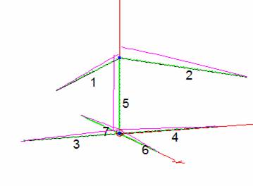
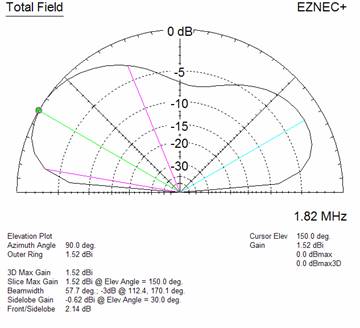
Note the large
current on the vertical feed line. This is typical of a vertical antenna. And,
if we look at the 3D radiation pattern, it has a bit of gain in one direction but
little radiation overhead. The model’s
predicted feed point impedance is 9 –j84 ohms.
A small real R of
9 ohms fits with a very short vertical antenna. Ditto the capacitive reactance
of -84 ohms, for a short antenna. According to this complex impedance, a
loading coil with 84 ohms reactance would resonate the
antenna, and all we would have to do is deal with the low radiation resistance
of 9 ohms.
If only life were
this simple! (Sigh) Now we have to look at reality.
Next step is to realize we actually have lots of
ground loss resistance and some inline inductance to deal with. So, it’s time
to dig out the analyzer and see what we really measure. I did roll out some
radials, 5 in this case and I can verify that they aren’t very good. I expect
very significant ground loss and efficiency issues. I have an Autek
RF-1 which gives typical results for a simple instrument. When hooked onto the
shorted feedline and the newly minted radials, we get 74 +j190.
And, the resonant frequency is 1.46 MHz.
What the …….??? Obviously there IS some inductance in those built in antenna
devices. This antenna has a line isolator mounted 20 feet below the antenna and
a customized balun at the antenna. Those devices are
clearly helping our cause, because now we have an electrically long antenna
that is resonate way below 1.82 MHz (where I measured everything). This is very good news !
BTW, the analyzer also shows a needed inductance of 18 uH
and a capacitor of 409 pF to bring it into our 160M
world. Remember those values for later!
Let’s see if we
can figure out what’s inside. Turns out I have a (
convenient) spare 80M Windom stored in my shop. Taking my analyzer in L
measuring mode to that unit shows the series inductance of the midline isolator
to be about 19 uH, or 217 ohms reactance. The top unit is a little more complicated,
but I estimate the inductance to be 1.5 uH and 17
ohms reactance.
Now we can plug
that into the model and see what changes. Yes, we can insert lumped components into
EZNEC models for just this eventuality.
So, here is a
new model view:
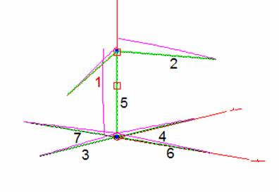
This looks OK. There are no weird discontinuities around
the two added loads. (The square boxes. The new
predicted impedance is 17 +j177, which is much closer to our measured value. In
fact, the reactance part is very close. Why do we show only 17 ohms for the
Real part, instead of the measured 74 ohms?
Well, that’s the bad news part. The model, in this case, doesn’t predict
the ground losses. They are real however, and are added to the radiation
resistance of about 17 ohms. Unfortunately, that means we have pretty big
losses in the ground. I am not going to deal with that right now, but want to
get this puppy on the air and see what’s happening. I didn’t do it here, but we
could estimate the value of the capacity hat on top by looking at the
difference in Z for a simple 48 foot vertical and calculating the value that
the top C must be to get us where we are.
The model is also
useful to probe around those loads during actual use and see what sort
of torture we are applying. Turns out I have a built in limit of about 600
watts, so applying that at the feed point shows the total coil losses of about
1.6 dB and a maximum voltage across the isolator reactance of about 1000 volts.
That shouldn’t fry the unit, but if it does, it’s easy to replace. Putting 1500
watts on this puppy could do some real damage though. No problems with QRP of
course. Caveat Emptor.
What else do we have to worry about before trying
this out? I have (had) another small 40M Windom mounted on this same mast,
about 6 feet below the big one. I can show those wires in the model. There is a
suspicion that capacity wires mounted lower down the center conductor could
alter the characteristics of the radiation pattern. And sure enough, it does.
It looks like that is going to cost us a few dB in output. I wasn’t using this
antenna anyway, so down it comes.
The match is produced after digging around in the
junk box. A variable cap is put in series with the antenna and the analyzer and
adjusted for the lowest Z I can get on 1.82 MHz. Turns out to be 384 pF in series. That
leaves the R of 74 ohms to deal with, and a variable inductor is inserted to
ground (Shunt) at the transmission line and adjusted for a low SWR for 50 ohms.
That value turns out to be 13 uH. Note how close
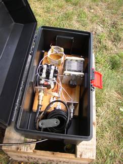
those are to the analyzer numbers referred to earlier. A cheapy
tool box makes a nice housing for the unit, which includes a relay to allow it
to switch between normal Windom mode and the new “Windovert” mode from inside
the shack. Plus a great ‘honkin’ choke for the
transmission line, and voila.. we
have a match !
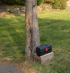
Note the “Cutty Sark” crate platform… a key
element to good DX on this antenna! Inside you can see the doings that make up
the L match. Since there is a series capacitor in line with the feed line, I
felt it prudent to install a 100 mH choke across this
cap to provide a DC ground for static. A large wattage and high value resistor
would also work. The choke is very high
Z at 1.82 MHz and won’t affect the signal.
Performance is a treat ! By
gosh, it works wonderfully. It hears well and transmits just fine. I have only
tried it with a few Eu and West Coast contacts so far
but it seems to do everything I need. How nice to finally be able to transmit
properly on 160M !
But wait… there’s more !
I accidentally discovered this thing performs well on 30M too ! It works much
better than my existing 30M vertical, and that isn’t surprising, considering it
has more physical length. In fact, it’s almost ½ wavelength
on 30M, and the feed point match still work perfectly. THAT is a happy
coincidence.
My last
modification was to move my short beverage away from the base of the antenna.
In fact, I have since deleted this beverage from my collection and moved to a
Beverage on Ground (BOG) antenna which gives good results on 160 when used with
a phase control device. Normally, the ‘WindoVert’ by
itself is the antenna of choice. It does make QRP contacts, although any QRP on
160 is a challenge.
If you are looking
to get on 160 from a small yard, and have a Windom or
a dipole that can be converted to a Marconi style antenna, this could be your
best bet for a simple antenna.
Good luck with
your antenna projects.. hope
to hear you on the low bands.