Part 2: More IMDR Adventures
Jeff Smith VE1ZAC
In part one, I
took a stab at measuring the IMDR ( Inter modulation
distortion dynamic range) for my
IC7700. I used a pair of HP8640A
generators that I have in my shop and followed the conventional methods of
doing this measurement. The numbers I got were around 80 dB. Several folks sent me notes on the effort,
including Adam Farson and some others who alerted me
to problems in using 8640’s for measurements like this. The problem is… these
generators have oscillator phase noise that is no better than about 80 dBc/ 1 Hz. Since we need signals that are sizeable in the
receivers passband to make IMDR measurements, there are problems with the phase
noise in the side bands mixing in the pass band and with the receivers local
oscillator noise bands and producing IMDR products.
Is this important ? Yes, and no. On the yes
side, if we truly want to make a good test that we can use to compare receiver
numbers, then we need a test that is not limited by the measuring equipment. In
this case I am really only interested in CW signals in close to our operating frequency, and 2 KHz seems to be the popular standard
spacing for this. We put two strong signals in our passband that are 2 KHz
apart and then listen for a distortion signal that is formed at a point 2 KHz
above the highest signal. The difference between the interfering signal
strength and the MDS number is the IM dynamic range in dB. The problem is.. we need very low phase noise
oscillators to make this test. On the
other hand, we should think about the reasons we do this test. The idea is to
give some idea about the rigs ability to deal with strong adjacent signals in
the receivers passband. These signals can be of two
types. One type is from a strong but clean transmitter that typically has low
phase noise when it gets to us. I won’t go into this here, but small amounts of
phase noise at the transmitter end are often left behind during the propagation
process. As a result, these kinds of signals are ‘Clean’. There are also plenty of less than high
quality signals that could be in our pass band as well. These ones are probably
better emulated with oscillators with more phase noise for a real life approach
to the test. It is perhaps of note to compare the two, which we will do later
on.
To make a long
story short, my first tests really demonstrated the limits of my workshop oscillators! The best IMDR numbers I got were in the 80 to
85 dB range, and were clearly phase noise limited.
Better Oscillators
Several evenings
of research provided steaming heaps of information on phase noise! I even dug
out my 1974 engineering text “Communications Circuits: Analysis and Design” by
Ken Clarke and Don Hess and studied up on issues affecting oscillator issues. Some great material is available from Wenzel
Associates web site. http://www.wenzel.com/
There is also a very good technical tutorial on phase noise at Oscillator
phase noise : A tutorial
These folks are
experts in low noise oscillators. I also perused my now very dog eared copy of
EMRFD by
I narrowed down my
oscillator circuit to either the recommended EMFRD one or a simpler one I found
at Wenzel’s web site. Here is a link to it : Low Distortion Crystal
Oscillator This one filled the bill for construction, but no actual numbers
for phase noise were provided. However, the source pedigree was excellent, so I
decided to give it a shot.
Construction
I have done some
two dozen projects using Eagle Cad ( free version) and
my little homebrew CNC Sherline conversion mill. As a
result,
this one turned into a one evening project.
Here is the EagleCad schematic and the board graphics. I used a one
sided board layout but used a double sided PC board to establish a nice ground
plane. You can remove some of the copper around component holes with a bigger
drill bit to prevent shorts. An effective technique.
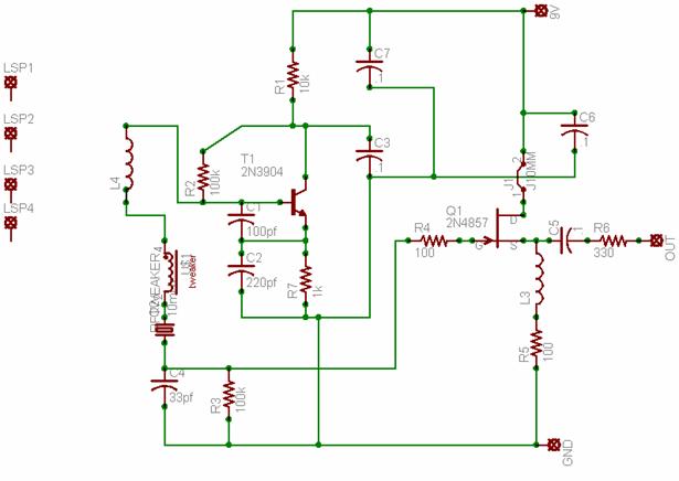
I used a J309 NFET
for the Q1 and NPO capacitors for C1 and C2, since I found some in my capacitor
collection. J1 is a jumper for a ferrite bead. L4 is 1.2 uH and
the TWEAKER is the primary of a RF
transformer I found with 3 uH primaries. This
provides a ready method of adjusting the frequency a little. In practice, it
was easy to get these guys to be 2 KHz apart.
Here is the layout
graphic: ( for one oscillator.. there are two built
onto a common PC board)
Testing
It fired up first time ! That doesn’t happen all that often for me, so it was pretty rewarding.
Nice big signals in the -5 dBm range too. Just what
is needed. I elected to go with 9 volt batteries to
make it as free of power line noise as possible, and very portable. Each oscillator
only draws 5 mA or so. Batteries will be fine for
testing receivers.
So, we are back to
figuring out the noise. I had a look around the laboratory I consult with and
discovered a couple of spectrum analyzers that should have the capability to make
phase noise measurements. This lab doesn’t do much RF work..
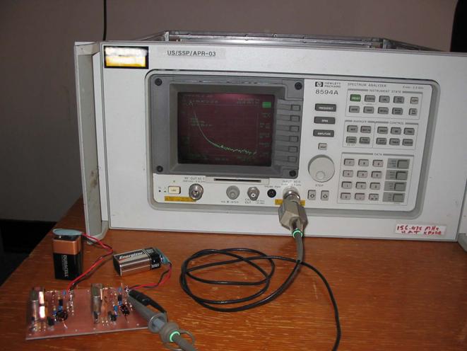
mostly acoustic work. But I did find one nice RF job…
an HP 8594A. This unit even has the noise measurement function built in to the
marker menu.. a very
convenient feature. Here it is hooked up
to one of my oscillators. You can see the noise function running on the screen.
The attenuation in practice is about 20 dB so the peak is around 0 dBm.
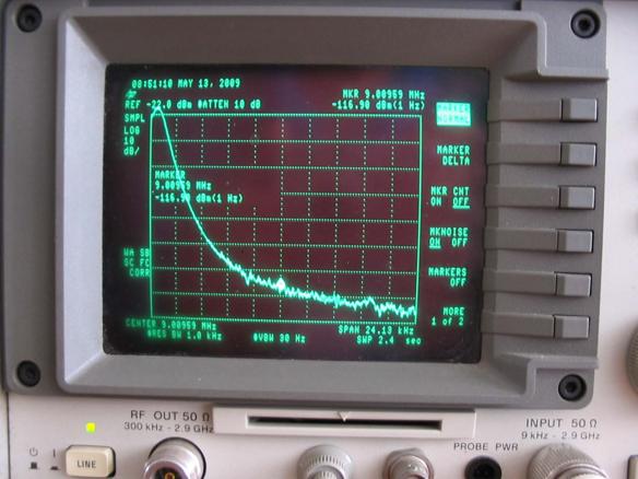
Here is a
photograph of the display. Note the noise marker reading and calculation of
-117 dBm/ 1 Hz. This winds
up actually translating into the noise spec of the spectrum analyzer of about
-90 dBc/ 1 Hz.
Drat.. we are limited
by the phase noise of the analyzer. But, we can say that our noise spec must be
pretty good.
I went through
this same procedure with two other analyzers. One had a noise spec of -108 dBc/ 1 Hz. In all cases, the measurement produced a number
that was limited by the spectrum analyzer. So, it looks like the noise figure
is at least as good as -108 dBc/ 1 Hz. If I can
locate a better analyzer, I will get a reading on these things, but for now I
am going to have to live with that upper range of the noise as the best I can
do.
Here is the
finished unit: 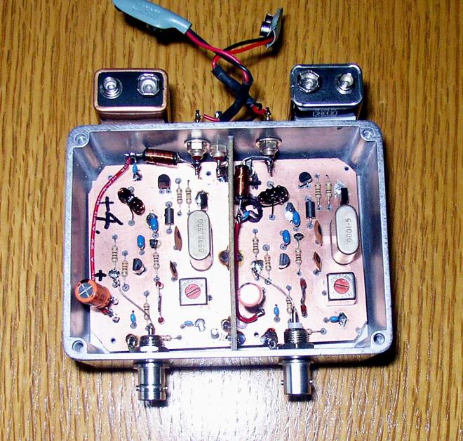
One oscillator has
an output of -7 dBm and the other has +1 dBm. An attenuator on the strong output easily brings the
two signals to the same amplitude for the IMDR test. The usual hybrid coupler
and attenuators are used as in the Part 1 article.
Tests with <108 dBc/
1 Hz oscillators:
MDS of -135 dBm and
IMDR of 98 to 100 dB. ( at 9 MHz, CW, 3
kHz roofing filter, 2 KHz spacing)
Previous tests with 80 dBc/
1 Hz oscillators:
MDS -121 dBm and IMDR of 80 dB. ( at 14
MHz, CW, 3 kHz roofing filter, 2 KHz spacing)
Conclusions:
- These are tricky tests, and a host of
calibration issues come up. So, let’s say our new IMDR tests are in the 95
to 100 dB range. This is very respectable performance, for clean signals.
- I still don’t know the actual noise
figures for the oscillators, but I suspect it is beyond what we need for
this test.
- “Dirty” signals will indeed cause more
IM problems in our receiver passband.
- The Wenzel folks know their stuff !
- You can build low noise oscillators
fairly easily.
- If you want really good IMDR numbers
for dirty signals, you probably need narrower roofing filters and
different IF scheme.
- While not the definitive answer for
IMDR testing, these tests do point to the high quality of the IC7700
receiver.
I have heard that
the ARRL latest test on the 7700 produced a number in the same range. That is
encouraging.
VE1ZAC