K9AY
Foreward
The previous portion of this story describes my attempt at building a home-brew K9AY system around a conventional Gary Breed configuration with the exception that my transformer was built to a design allegedly superior to the original. It had no pre-amp, I never did figure out which way it was pointing when I rotated my azimuth control switch, and it had a fixed terminating resistor. It was adequate, though to satisfy the purpose behind the project which was to experiment with this kind of antenna and evaluate its usefulness as an addition to my antenna farm at my contest station.
My developmental system suffered from a couple of shortcomings, one of which is that it had that fixed terminating resistor. Trying to determine the optimum value for a single-termination system ain’t easy. I had settled on a resistor value in the 800 ohm range which (I now believe) was likely too high, because I couldn’t refine the number to any better degree. And right from the start I worried constantly about the suitability of that value and I knew I was not going to be happy until I could assess other values in real time.
The second shortcoming was much worse: shortly after I commissioned my prototype, it suddenly seemed to have lost its direction-switching capability, a problem isolated to a sticky open-contact relay at the antenna. This was in the winter, of course, when no amount of motivation would take me outdoors for any repair more sophisticated than a sharp rap to the relay box with a stick of well-frozen firewood. Notwithstanding these shortcomings and lack of confidence in the system on my part (because of the intermittency), what I could and did safely conclude about my prototype K9AY was that for my small contesting station using deliberately simple antennas and living with the usual domestic (electrical!) noise issues, it was a necessary tool if I were to squeeze every contesting erg of performance out of my amateur radio system. Indeed the first day I used my simplistic model I was able to operate on 20M in the 2009 CA QP California State contest when the band was otherwise entirely lost to me on every single one of my other four choices of decent antennas, the signals all the victims of noise.
This year, I completed to my satisfaction an analysis to substantiate a commercial purchase of something with more capability. The experiment had taught me what device to look for, how to knowledgably assess its performance, and what to expect, and I knew the news with the AS-AYL-4 was all good. Furthermore I could justify the expenditure on the grounds that I put enough sweat into the developmental project to merit the reward of having someone else do a nice job, beyond my capability, for the final product. Hence, I elected to retain the antenna per se but replace the electronics in the form of the remote antenna relay box and the in-station K9AY controller by Array Solutions K9AY Equipment Model AS-AYL-4.
Here some observations regarding this upgrade, in no particular order:
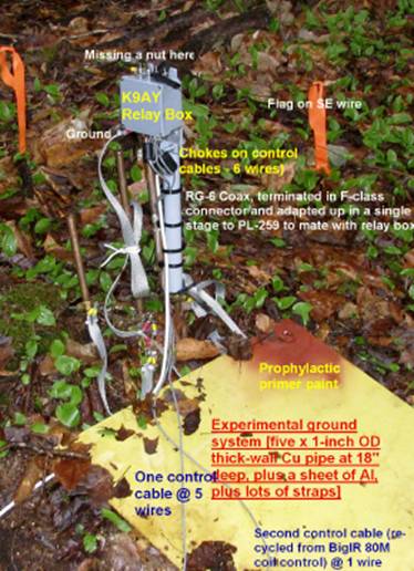
- Control cable: My K9AY used a single 5-wire cable. The AYL-4 requires six wires. To get where I needed to be, I re-used one wire from a outside control cable from an earlier project, carefully saved for a job like this because it already ran through the wall of the house!
- The Electric Fence: The neighbours have horses. This year they installed an electric fence around the paddock. While this has not been a problem to me because the K3 DSP Noise Blanker is very good, that fence proved to be a good source of noise to test the Array Solutions K9AY. Two interesting things resulted from a test on 20M:
- The electric fence noise was greatest on the K9AY, loud on the 80M dipole which is parallel to the fence, and surprisingly loud on my vertical. On the other hand, it was completely indiscernible on my full-size 160M vertical delta loop which is by far the closest to the electric fence and which is looking right at it off the feed end of the antenna. The delta loop antenna pattern from EZNEC shows that the gain of the antenna off the feed end (i.e., towards the electric fence) is almost the same as from the other direction (not much of a null on 20M with that antenna, which is fed at a corner) and therefore I have concluded that there is merit to the argument that wire delta loops can be quieter than dipoles.
- I have verified the new loop system’s sense of direction (OK, my own sense of direction). That is to say, I know the electric fence noise source to be located physically southwest of me and, sure enough, that’s where the loop controller switch is pointed – at the source, not the null. I even now have an indicator light that says so!
- Antenna Grounding: At the moment, I have a fortune tied up in copper at the antenna site. In addition to the original five lengths of copper water pipe at a depth of only 18”, I have added a 2-foot square plate of thin scrap aluminum that I had here (additional capacitive coupling to the earth), and today I added 8 radials of about 15 feet teach. All those grounds and a whole bunch of strapping. Everything is working rather well right now and I am loath to monkey with that grounding configuration. But some day I will. See below for a picture of this monstrosity.
- Mounting of Relay Box: I simply made two shims from a wall section of 2-inch PVC and using a short length of 1 ¼ PVC pipe, mounted the relay box to that using the supplied I-bolt and bracket, and dropped the complete assembly over one of the existing copper antenna ground rods where it is allowed to float. The wire ends of the two loops, once connected to the top of the relay box, come a little close to each other in one place so I slipped some tubing over each of the two adjacent wires as a matter of good installation practice. Environmental protection is important around here and I have ensured that the relay box has a drain hole, that connectors are properly protected, and a cover for the assembly will be added. Thick-wall vapour barrier plastic makes good umbrellas.
- Antenna Suspension System: My friend Bruce VE1NB and I noticed that my loops, installed last year, were now sagging a bit from the fact that one of the supporting trees had been partly uprooted in a wind storm. When I checked it out later, I discovered the antenna in great shape but the bungee cords at each end had failed from over-extension, as one might expect. Once again this method of attachment has shown itself to be the best way I have learned to keep wire antennas in trees – build them with a weak point designed to deliberately fail under unusually high, rapid mechanical loads. Do that at an accessible wire attachment point and thereby protect the antenna and make repair easy. Light-duty Tie-Wraps make great frangible “fuses” as well.
- Chokes: I have them everywhere.
On the control cables, on the coax; both in and out. Lots of them. (Not shown on the feed
line in the accompanying photo).
- Coaxial Shield Grounding at Antenna
The original K9AY design used an autotransformer at the antenna output and
accordingly the shield of the feedline back to the shack was tied to
ground at the antenna, along with one side of the transformer, providing a
path for common mode interference.
Further experimentation (by others) showed that the antenna was
frequently quieter if the ground arrangement was removed and the shield of
the coax tied only to the secondary of the transformer. The usual practice on the Array
Solutions K9AY antenna relay box is to perform the ground isolation
modification and that involves the cutting of circuit board traces and
jumper wires. This seemed to be too
drastic an action to me so I modified the relay box with a DPST switch
that makes the modification but allows me to revert to the original configuration. To date, albeit in the early days of
evaluation of this newer system, I have seen no difference between the two
grounding approaches.

How Well Does it Work?
That is, in fact, an easy question to answer if one starts with this contester’s mentality. Namely, almost everything that has been added to this station has been added with single-mindedness of purpose: to maximize the performance of a small contest station. I count it a success if I can conclude, without fooling myself, that a new investment has increased my chances at getting a rare multiplier in a contest, even if only by a little. The K9AY does that for me, better than I hoped. So, “How well does it work?” you ask. It works well enough to keep, that’s how well.
I have been prepared to accept failure in some of my improvement attempts but, like every other antenna I have erected here, the K9AY loop (past and present designs) soon proved that, sooner or later, it would be the only antenna on the whole farm that would do the job. Therefore, it has added something to my contesting edge that I didn’t have before. It’s clearly a keeper. Here are three examples to support the decision:
Earlier this afternoon, I demonstrated that I can use my loop to reduce the level of signals on 20M coming at me from New England by about 20db (down now to only 40 over ;). This will be very useful during EU contests where I typically get beaten to death from my bigger brothers to the SW. This will make life less fatiguing for an operator in a long contest. The K9AY is justified as a keeper on the basis of that characteristic alone.
Shortly after that determination, I saw a spot for an OA on 12M. Even with a K3 I was not able to get the SNR down to the point where I could copy him on any other antenna. My new K9AY, using a smaller terminating resistor value than normal, reduced the noise level (which I think was atmospheric) to the point where copy became no-BS solid. An antenna that can do that once can do it again, maybe at a critical point in a contest. Another reason to keep it.
Early testing on 20M during the day has shown that the K9AY was very frequently the best receiving antenna of everything I have, bar none, and frequently there was enough front-to-back to be useful. Third reason to keep it.
That’s enough reasons.
Odd Things
My antenna coach was horrified to discover
how little I cared about this, but the fact is my installation of the K9AY – AT THIS STATION – is no darn good on
the Broadcast band. Too
noisy. I can’t use the BC band
for contesting and Short Wave Listening on that band is not a priority for me, so
this short-coming is no big deal.
Nonetheless one cannot help but be a little curious about the tricks one
might be able to play with a directional receiving antenna in the BC AM
mode. I wondered if I could really
separate
I tried that mode with the new K9AY hardware just like I had with my own prototype and discovered, not much to my surprise, that the K9AY continued to be on the far side of useless on the BC band in this station. Signals were obscured by a most god-awful agglomeration of broadband and discrete noises. Today, acting on an impulse from VE1ZAC who mentioned antenna interaction, I pulled the ladderline that feeds the 80M dipole from its matching unit in the shack and observed that the amount of noise on the K9AY loop dropped drastically. When I pulled the other ladderline from the adjacent transmatch that feeds the delta loop, it dropped by another order of magnitude, down to what one might call a normal or expected level for a proper-working loop. Clearly any inferior performance of my K9AY on the BC Band is a factor of its location and interaction with other antennas, not a limitation of the equipment. As a perfect example of antenna system interactions, this one cannot be beat.
I do not know where this noise originates
and by what mechanism it gets into the K9AY system and of course I would love
to. That it in fact happens at all,
though, should not be too mysterious because my K9AY is located waaay too close to one of the larger deposits of copper and
aluminum in the
Some night when no-one is watching, though,
I’ll disconnect the HF wires and see how the loops can do on the B.C. band when
given a decent chance. Or, as
recommended by Array Solutions, I might add a relay to automatically remove the
termination of the feedlines at the station end when listening below 1.8
MHz. I’ve been looking for an excuse to
add the Elecraft KRC2 Band Decoder and Controller to the K3 – perhaps this is
it.
REPEAT OF AN EARLIER DISCOVERY One
should never expect consistency from listening antennas, in my experience. Both the reversible Beverage and the K9AY
loop demonstrate a frustrating variability.
What is a winner today will be a loser tomorrow under what seem like identical
circumstances. Never the same twice. The extremes are dramatically good and
dramatically useless. Furthermore, your
friends will never believe your successes because there is a corollary to
Murphy’s Law which dictates that propagation will preclude you from ever being
able to demonstrate a listening antenna to another ham. Listening antennas only demonstrate their
remarkable capability around you (and non-ham relatives) and you can count on
them refusing to work for you when they know they are being watched by
knowledgeable outsiders.
CONCLUSION
This has been a most satisfying project. I had the good fortune of being able to build a model of an antenna that both worked and that demonstrated its worthiness to my contest station, during which time I learned enough about that world to take an informed longer-termed solution. And the final system looks nice from one end to the other!
As usual, kudos to Bruce VE1NB and Jeff VE1ZAC who in reality cause all this stuff to happen in my station which is, to a large degree, their design.