Diode Protection of Varactor CDS Resistor element in Loop
Terminations
Jeff, VE1ZAC
The following control element , Figure 1, as recommended by Mark Connelly, and other Pennant experimenters, is modified and built into a Pennant terminated loop at my QTH. Figure 2 shows my modified control element. The control element is a Perkins ElmerVTL5C4. The resistor side of the device is coupled to the antenna elements through .1 uFd capacitors. The elements are used as a DC path to provide the LED current to control the varactor. The DC is decoupled from the antenna elements through 80 mA , 2 or 3 mH chokes.
Figure 1: Basic Varactor element in loop
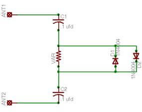
Figure 2: Addional components around the Varactor Resistor
( Inductors and Varactor Photocell not shown here, are same as Figure 1)
Figure 2 is a representative schematic of the element. There is no DC current that can flow through the protection diodes. Two different kindsof diodes are possible. The ubiquitous 1N4004, or its variants, and fast recovery diodes which have quite a bit faster frequency response.
To see if there are major issues with the diode protection, a model of the circuit was hooked up to a vector network analyzer (HP 3589A) and a return loss bridge and swept from 100 kHz to 7 MHz with power levels of 0 dBm and -20 dBm. ( dBm is a milliwatt of power into a 50 ohm load, quite high for normal reception conditions in an inefficient antenna like a Pennant)
The following are the results of the sweeps:
1)1N4006 diodes, 0 dBm, non-normalized response, varactor set at 800 ohms..
You can see that the response is exactly the same except there is a drop in level of approx .04 dB throughout the range. This is a negligible effect as far as receiving.
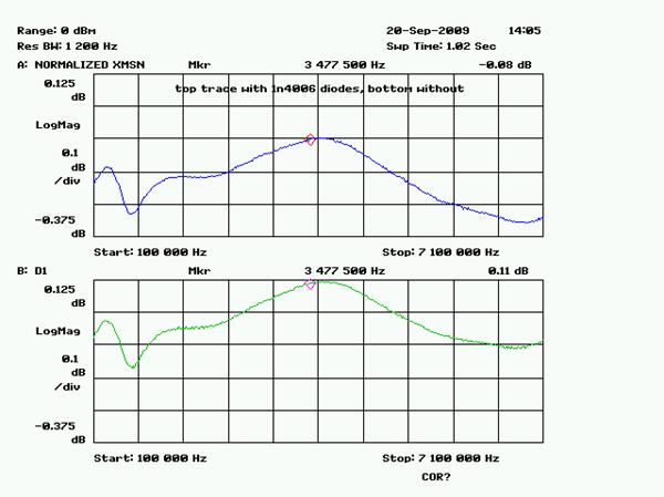
2) Here is the same response with normalized transmission, which is more useful for comparison purposes:
With the normalized traces, we can see that there is a slight attenuation proportional to frequency rise. It is maybe .1 dB at 7 MHz, negligible. This for the regular diodes and for 0 dBm power levels. The diodes are not turning on for us here. What we are seeing is the addition of a shunt capacitance across the resistance, provided by the diodes. The analyzer upper limit for power source levels is 0 dBm, so that is as high as we can kick the diodes with RF energy.
3) Let’s try the same thing with fast recovery diodes (FRD’s):
No noticeable effect through to 7 MHz.
4) Let’s do one more with the FRD diodes and reduce the source level to -20 dBm. ( 100 times smaller, but still a big signal)
In this one, the no diode condition ( green graph) has been re normalized. You can see there is no effect with the diodes in place.
Conclusion:
It looks like either diodes could be used for normal reception in a DC blocked circuit like this one (coupling capacitors to the resistance of the varactor, no DC flowing). The FRD diodes are going to provide a limiter function at a greater dynamic range. I would choose the FRD’s and in fact I will install them in my unit at first opportunity and see how they perform. They will limit the energy across the resistance to about .5 volts. Depending on where the resistance is set, the energy will be limited to V^2 / R .. a pretty small value.
NOTE: This advice only applies if the varactor element is AC coupled to the antenna element. If it is direct coupled, there may be DC currents flowing through the element and the diodes in some cases. Frankly, I have no idea why anybody wouldn't use AC coupling to protect a low wattage device like this. And the diodes are highly advantages to limit power that the device sees under nearly any condition... save a direct lightning strike in the vicinity.
October 2012 Comment: Dallas Lankford mentioned the risk of IMD being generated by the protection diodes. This is indeed a possibility, especially if you live near large broadcast transmitters. I have not detected any problems with my setup, so far. However, it is something to be on the watch for. It's possible the high speed high current diodes I am using are particularly good in this regard. That would be a happy coincidence. I will put on my project list sweeping this circuit with my spectrum analyzer with higher source levels and see what might be going on with the diodes.
