Adding a Director to a ¼ wave 40M HF vertical antenna
Jeff , VE1ZAC
This is not a new idea, but the method I am suggesting of doing it is novel, and possibly simple to implement ! The caveat is that it is fussy and unique to each antenna situation.
This article describes a 40M vertical antenna director, but first we need to time travel to the distant past…………
Background 1): Some 10 years ago I was very interested in the idea of a ¼ wave vertical yagi that could be rotated. There are lot’s of objections to this idea, the main one being that a ¼ wave antenna is just that… a ¼ wave antenna. It still functions like a dipole, but the other half of the antenna is a “Virtual” or imaginary antenna that resides within the antennas ground system. To an RF observer that is located some distance from the antenna there is a vertical dipole in place, not part of one. A visual observer would see only part of one. Of course, the virtual part of the antenna in the ground is associated with the attendant ground losses from the quality of that ground. ¼ wave vertical antennas nearly always have losses that exceed a vertical dipole that is standing free and clear of the ground. However, unless the antenna is mounted a substantial distance from the real ground ( IE, more than ½ wavelength) the ground still has an effect on the radiation characteristics of the antenna system.
Jerry Sevick, a well known antenna and broadband transmission line transformer expert wrote an article in QST some years ago about his experiments with a ground plane Yagi. Think of this as ½ of the common place 3 element Yagi stuck in a ground plane. Another article in one of the ARRL Antenna Compendiums described the construction of such an antenna using trapped elements to allow use on three bands. Both of these antennas were successful projects and produced desired beam pattern, gain and front to back ratios. Both experimenters found the radial field for all three elements was crucial, as one would expect for any 1/4 wave antenna.
Background 2): Having an overly fertile ( or weird) imagination, I wondered if one could make a steerable version of this antenna. Why ? Well, it would be compact if made for 20M or above, and the mechanical parts of this thing would be much simpler than the needs of a tower mounted antenna. It would have pretty low take off angles for DX use. Also, I had a cheap TV antenna rotator lying around, begging to be used for something. And the idea of a short steerable antenna kind of caught my fancy. It would also be close to the ground and would therefore have some stealth aspects. The real problem would involve the missing ground for a director and /or a reflector. Assuming the rotator sat below the radiating element, it’s ground shouldn’t be a problem. But.. any out board parasitic element that swings around on a boom will be a problem.
Or will it ? A normal Yagi uses elements that are a little longer or shorter than the driven element.
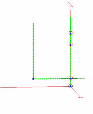
Here is a starting point model from the ARRL Compendium article. The elements are mounted on a good ground in this case, so no radials are shown. For simplicity sake, I will stick with the use of a simple ground model to compare models.
 Notice the three elements
with the traps represented by the red boxes. To model those at a specific
frequency, you must input the traps complex impedance at that frequency. This
particular test is at 14.1 MHz, which was my prime interest anyway. It showed
about 3 dB overall gain, and some decent F/B ratio. The left element is the
reflector, center a driven ¼ wave element and the right a director.
Notice the three elements
with the traps represented by the red boxes. To model those at a specific
frequency, you must input the traps complex impedance at that frequency. This
particular test is at 14.1 MHz, which was my prime interest anyway. It showed
about 3 dB overall gain, and some decent F/B ratio. The left element is the
reflector, center a driven ¼ wave element and the right a director.
 Well, that’s fine and
dandy, but I wanted a way to rotate this thing on the ground. So, onwards to the start of some bizarre ideas.
Well, that’s fine and
dandy, but I wanted a way to rotate this thing on the ground. So, onwards to the start of some bizarre ideas.
Rotating the parasitic elements: I had lots of impractical ideas, but eventually realized the only practical way to do this was to use a boom like a real Yagi. But what was going to happen to the ground for that element ? There would still be a ground of sorts, but since it wasn’t at the same reference as the driven element, there is no way for circulating currents and virtual dipole halves to come into play. And sure enough, it didn’t.
 The parasitic elements
have been shortened to get the model to work at all, and it doesn’t radiate
well. The radials shown were an attempt to show how they might come into play,
as in real life there is a decent radial field below this antenna. ( Or was… hurricane Juan took this thing out). The boom is
now part of the parasitic element and actually shows current on it when you run the model.
However, I was sufficiently encouraged to see that there might be some
possibility of getting a “Swinging” parasitic element to work.
The parasitic elements
have been shortened to get the model to work at all, and it doesn’t radiate
well. The radials shown were an attempt to show how they might come into play,
as in real life there is a decent radial field below this antenna. ( Or was… hurricane Juan took this thing out). The boom is
now part of the parasitic element and actually shows current on it when you run the model.
However, I was sufficiently encouraged to see that there might be some
possibility of getting a “Swinging” parasitic element to work.
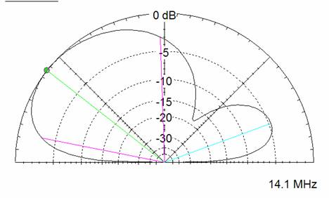
Enhancing the model: Here is a version with a trapless
set of elements, for 14.1 MHz only.
Surprisingly,
the longer element on the left is now the director, and the one on the right is
the reflector. But, the gain of this
thing shows about 6 dB now ! I did build this one and
it became known as “Jeff’s
 Another blast of modeling
convinced me of a learned truth: one parasite could be almost as good as two, and a darned sight easier to implement.
Another blast of modeling
convinced me of a learned truth: one parasite could be almost as good as two, and a darned sight easier to implement.
This
one has a director parasitic element and has a decent gain of about 5.5 dB but at a
slightly elevated takeoff angle. So be it. I stayed with this one as a useable
antenna, and happily made contacts with it until Se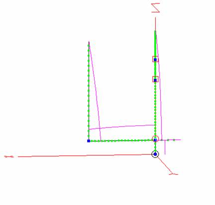 ptember 2003. I only used
it on 20M, with a dedicated director on the boom. This one was made with an adjustable length
director and could be tuned for the drop in impedance at the feedpoint of the driven element.
ptember 2003. I only used
it on 20M, with a dedicated director on the boom. This one was made with an adjustable length
director and could be tuned for the drop in impedance at the feedpoint of the driven element.
The boom is clearly part of the director. Here is a plot showing the currents on the elements.:
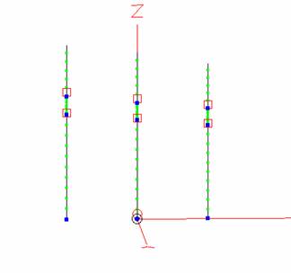
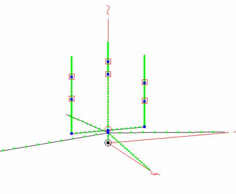
Now let’s flash forward to 2007, wherein, VE1ZAC, VE1NB and VE1RGB all have 40M verticals of one form or another and I have succeeded in converting NB and RGB to the wonders of EZNEC modeler.
The
verticals in play !
Bruce, VE1NB has a vertical antenna farm and last year Gary, VE1RGB decided he needed a vertical for that oh-so-desirable low angle DX on 40M and up. He got talked into a Steppir adjustable vertical and has had a year of snagging all the local wildlife in his radials and having fun chasing DX with the antenna. However, the subject of vertical pointyness reared it’s head again ! The choices to take an omni directional antenna into the world of beams is to make an array of some sort of additional elements. And these usually boil down to extra elements that have controlled phase angle feed lines, or parasitic elements that have phased signals courtesy of close in mutual inductance.
At
the same time as
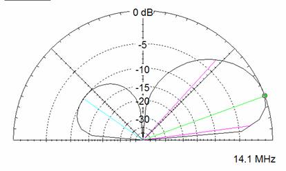
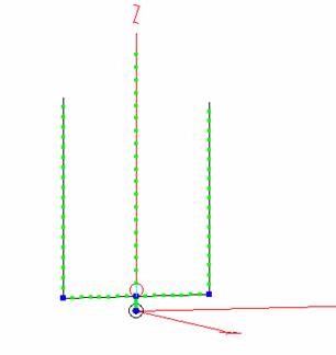
Soooooo… a quick revisit to my old 20M rotating parasitic array was in order. Turns out there is mention of this sort of thing in John Devoldere’s new book as well ( Low Band DXing). A quick model session.. and voila ! We have a simple ( VERY simple) director for this antenna, and about 3 dB of gain !
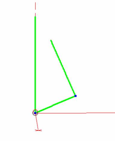
 Here it is:
a simple wire that is attached at the base and held up by a fishing line
halyard to the top of the mast, and another piece of fish line to hold the apex
out from the base. This is a director, so it points in the direction you want
to steer… like a big arrow!
Here it is:
a simple wire that is attached at the base and held up by a fishing line
halyard to the top of the mast, and another piece of fish line to hold the apex
out from the base. This is a director, so it points in the direction you want
to steer… like a big arrow!
Since the feedpoint impedance will drop precipitously when the coupling occurs properly, it is easy to adjust this thing by putting an impedance meter at the feedpoint and pulling the bottom leg around until you get a nice low reading. Worked like a charm. My model dimensions were just about right on. Even better, the new feedpoint impedance was about 25% of the original. Why is that a good thing ? Makes matching easy, as I will explain further on.
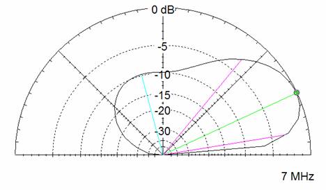
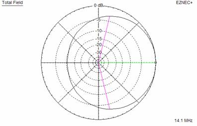
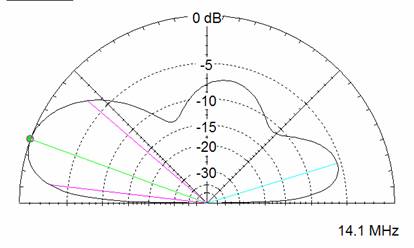
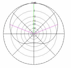
So.. here is the theoretical radiation patterns, but I have no evidence yet that they are exactly like that. My antenna is in a poor location and has lots of things in the near field that might distort the pattern.
However.. I walked around the antenna with a field strength meter, and
sure enough… lot’s of radiation in front, and very little in back. Plus, in operating I can
confirm that the beam is headed NE in the direction I planned. In the evenings,
I can easily cut the
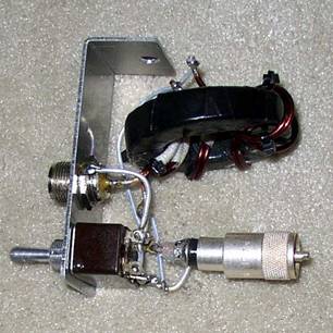
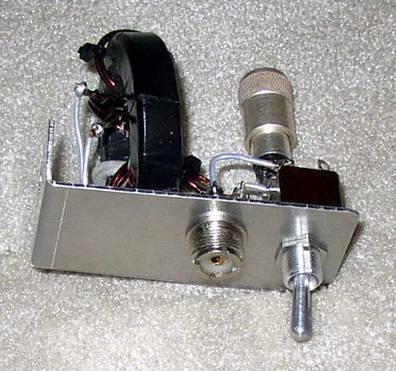
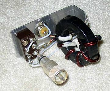
Here are some shots of the parts:
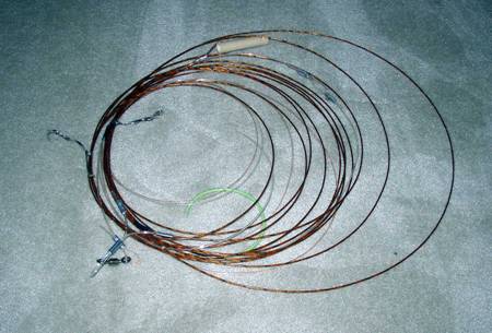
The element is hunk of surplus F18 aircraft hookup wire that I use for antennas ( Our club sells surplus stuff donated by IMP.. cool wire.. has that controversial Kapton insulation too) . I routinely use 300 lb. monofilament fish line and gear for antennas. Works great. Around here this stuff is used for trawl fishing gear. Nice SS swivels and clips are all readily available and cheap.
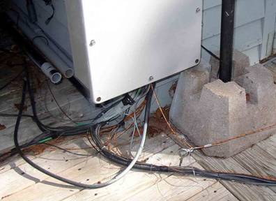 Here is the base leg
heading into the matching unit. The screw eye is used to adjust the strain
relief line.
Here is the base leg
heading into the matching unit. The screw eye is used to adjust the strain
relief line.
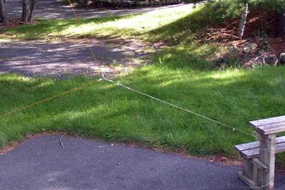
On the right is the apex hooked to a convenient step. Steering is easy ! Move this support around the antenna !
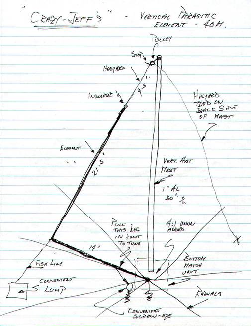
And of course… here is one of my famous high quality drawings of the actual parts and dimensions. ( I figure these sketches of mine will be famous in several hundred years… maybe I should write my notes backwards ? Naw… nobody can read my squiggles anyway)
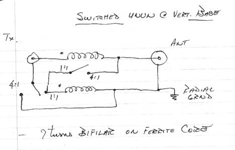
The matching problem: Of course the feedpoint impedance is going to drop with a parasitic element. My model showed it to be about 25% or so, and that’s what it turned out to be. Well, if that’s the case, then a 4:1 UNUN transformer should match the thing handily to coax. Turns out I already had a 1:1 UNUN out there to isolate the coax feed line, so it turned out to be easy to add a simple switch at the base to allow me to switch the transformer from 1:1 to 4:1 This isn’t a very sophisticated UNUN, but it works fine for this job. In my case, I had a nice coax connector under the weather shield, and it was easy to insert this thing in series with the coax. I just reach under and flick that switch to change the impedance.
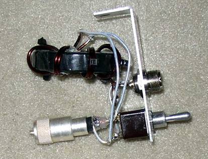
It takes , literally, 5 minutes to pull the director up and switch the transformer, including the walk over to the antenna !
As usual, if anyone tries any of these ideas out, please let me know the results.
Jeff VE1ZAC
References:
1) Low Band DXing, 4th Edition, John Devoldere,
ON4UN (ARRL Press), Chapter 13.
2) The W2FMI 20M Vertical Beam, Jerry Sevick,
QST June 1972
3) A TriBand
Parasitic Vertical Directional Array, Walter J
Schulz, K3OQF, ARRl Antenna Compendium Volume 1